Bonding method and bonding apparatus

a technology of bonding apparatus and bonding method, which is applied in the direction of welding/soldering/cutting articles, welding/soldering apparatus, manufacturing tools, etc., can solve the problems of reducing the and reducing the size of the bonding apparatus. , to achieve the effect of simplifying the configuration of the bonding apparatus, reducing the size and eliminating the influence of the shutter on the conductive elemen

Inactive Publication Date: 2009-01-01
TDK CORPARATION
View PDF2 Cites 12 Cited by
  • Summary
  • Abstract
  • Description
  • Claims
  • Application Information

AI Technical Summary

Benefits of technology

[0033]Furthermore, the conductive element is pressurized and attached to the opening, and is projected by supplying a compressed air such that the compressed air exceeds a frictional force between the opening and the conductive element. Accordingly, it is not necessary to provide another member for holding the conductive element in the nozzle, and it is not necessary to synchronize another element and the heat radiation emit

Problems solved by technology

However, as the electrodes are becoming smaller, it is becoming difficult to carry and melt the solder ball 707 using the suction nozzle 700 and the optical apparatus 710 without contacting other electronic components.
Also, in the soldering apparatus of Japanese Patent Applicati

Method used


Image

  • Bonding method and bonding apparatus
  • Bonding method and bonding apparatus
  • Bonding method and bonding apparatus

Examples


embodiment 1

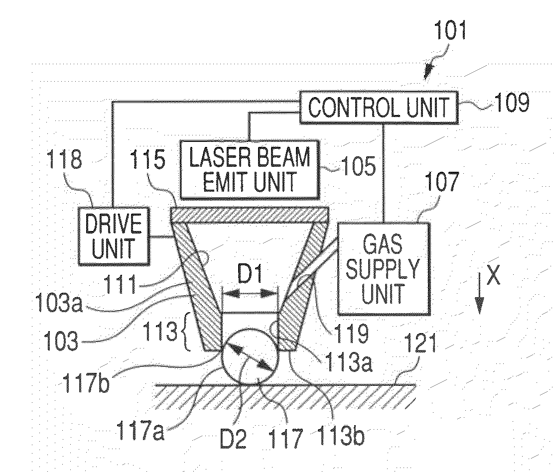
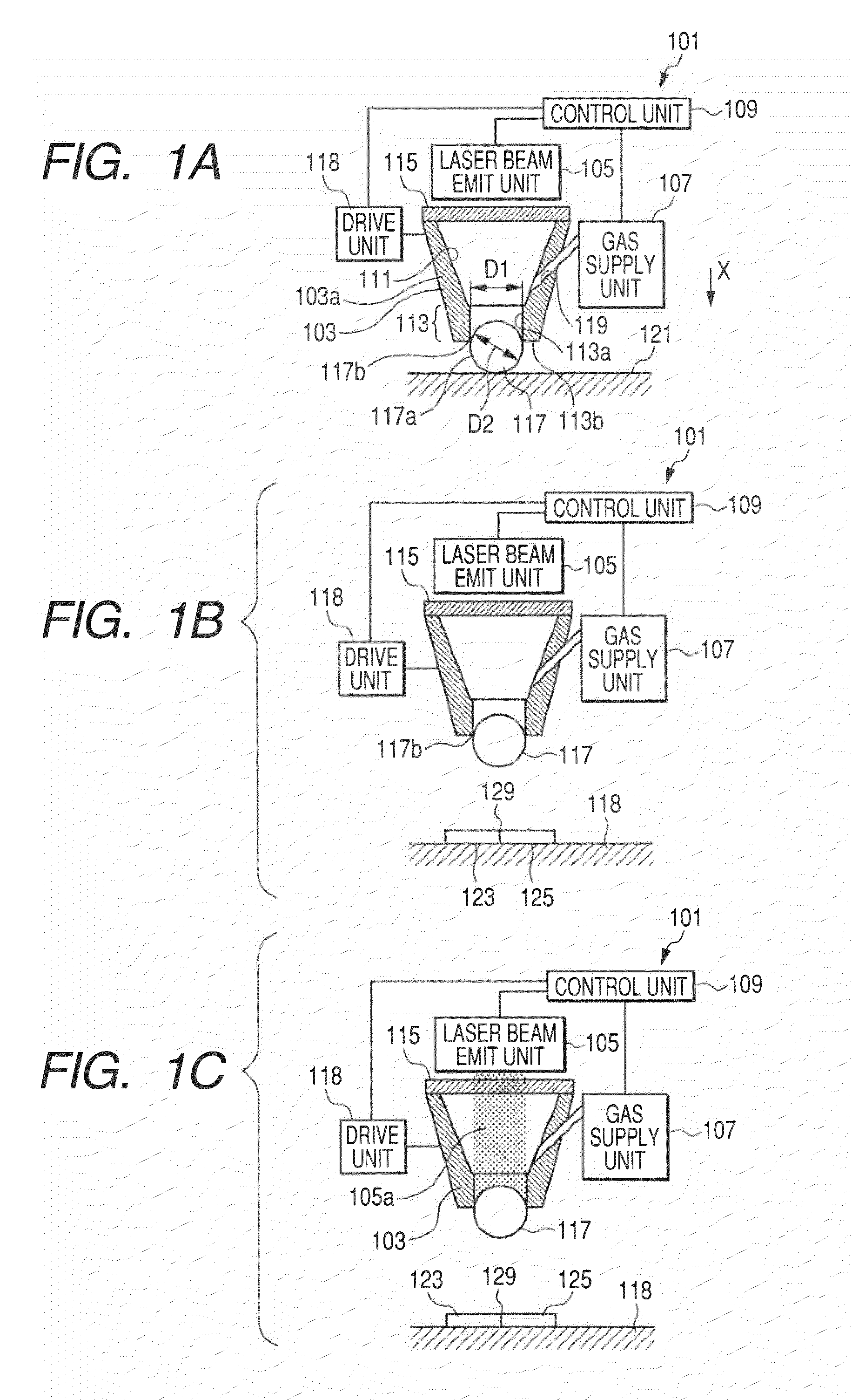
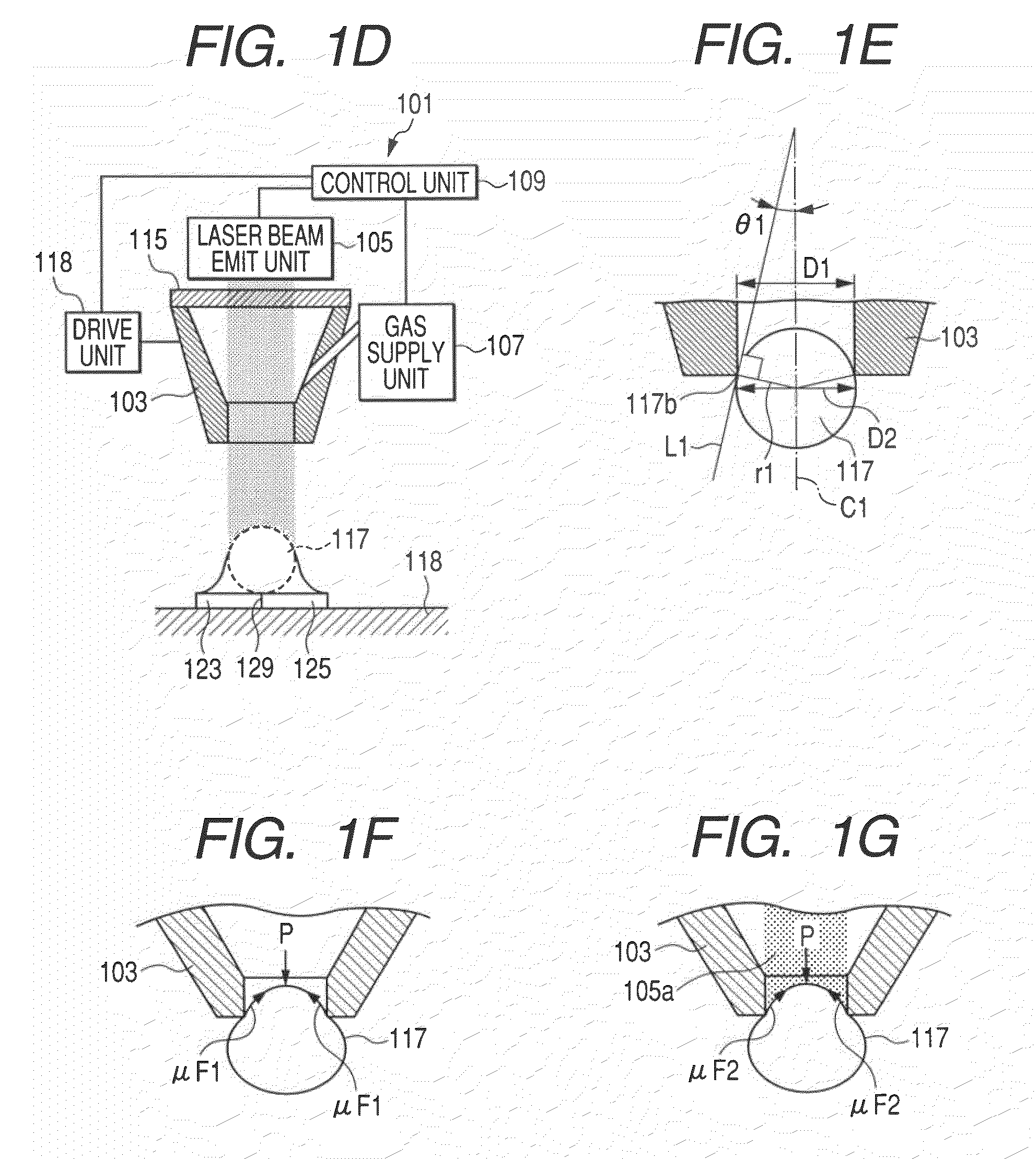
[0048]FIGS. 1A, 1B, 1C, and 1D are partial cross-sectional views in respective soldering steps of a soldering apparatus according to an embodiment 1. FIG. 1E is a cross-sectional view illustrating the relationship between a nozzle and a solder ball in the embodiment 1. FIGS. 1F and 1G are cross-sectional views respectively illustrating the state of a force acting on a solder ball pressurized and attached to an opening. FIG. 2 is a flowchart of a soldering process.

[0049]As shown in FIG. 1A, a soldering apparatus 101 mainly comprises a nozzle 103 for projecting a solder ball 117, a laser beam emit unit 105, a gas supply unit 107, a drive unit 118 (namely, pressure and fit means) for moving the nozzle 103 and pressurizing and fitting the solder ball 117 thereinto, and a control unit 109. The nozzle 103 comprises an inner space 111 therein, through which a laser beam described below passes and into which a compressed gas is supplied, and is a cylindrical member which opens at both ends ...

modification 1

(Modification 1)

[0067]A modification of the embodiment 1 will be described. FIG. 3 is a cross-sectional view of a nozzle according to the modification 1. An opening 213 of the present modification has a shape widening toward the top unlike the embodiment 1. That is, the opening 213 has such a configuration that the inner diameter increases gradually from an inner space 211 side toward a top end portion 213b.

[0068]In the state in which a solder ball 217 is pressurized and attached to the opening 213, the solder ball 217 is pressurized and attached such that a diameter portion 217a which is the maximum dimension portion of the solder ball 217 is located closer to the top end portion 213b side than an abutment portion 217b of the solder ball 217. With the configuration as described above, even if there are variations in the dimensions of the solder balls to be used, it is possible to locate the maximum dimension portion 217a closer to the top end portion 213b side of the nozzle than t...

embodiment 2

[0070]An embodiment 2 is a soldering apparatus using suction means as pressure and attach means for pressurizing and attaching the solder ball to the opening, and will be described below with reference to FIG. 4. FIG. 4 is a partial cross-sectional view of the soldering apparatus according to the embodiment 2.

[0071]A soldering apparatus 301 mainly comprises a nozzle 303, a laser beam emit unit 305, a gas supply unit 307, a control unit 309, and a suction unit 325 which constitutes the suction means. The laser beam emit unit 305, the gas supply unit 307 and a gas introduction path 319 have the same configurations and operations as those in the embodiment 1, and therefore, the descriptions thereof are omitted. Also, for simplicity of the drawing, a drive unit having the same configuration and operation as that in the embodiment 1 for moving the nozzle 303 is omitted from the drawing.

[0072]The suction means comprises the suction unit 325 which is a well known vacuum pump or the like, a...


PUM

PropertyMeasurementUnit
Pressureaaaaaaaaaa
Diameteraaaaaaaaaa
Radiusaaaaaaaaaa

Abstract

The present invention relates to a bonding method or an apparatus for projecting a conductive element from a nozzle onto an object to be bonded and electrically bonding the object to be bonded and the conductive element. The method of invention comprises the steps of: preparing the conductive element having an outer diameter with a curvature radius larger than a curvature radius of a portion of an opening of the nozzle which is in contact with the conductive element; pressurizing and attaching the conductive element to the opening of the nozzle; and supplying a compressed gas into an inner space of the nozzle and projecting the conductive element in a solid phase state onto the object to be bonded.

Description

BACKGROUND OF THE INVENTION[0001]1. Field of the Invention[0002]The present invention relates to a bonding method and a bonding apparatus for electrically bonding a conductive element and an object to be bonded.[0003]2. Related Background Art[0004]In a process for manufacturing magnetic heads, an electrode of a magnetic head slider and an electrode of a flexure are bonded by soldering by using a solder ball. More specifically, electrical bonding of the electrodes is performed by disposing the both electrodes with an angle of 90 degrees therebetween, disposing a solder ball between the electrodes and melting the solder ball by heat radiation or the like. Conventional solder ball soldering apparatuses will be described below with reference to the drawings.[0005]FIG. 11 illustrates a first conventional soldering apparatus described in Japanese Patent Application Laid-Open No. 2002-25025. In the drawing, reference numeral 709 denotes a substantially rectangular solid slider, and referen...

Claims


Application Information

Patent Timeline
IPC IPC(8): B23K11/00B23K11/24
CPCB23K1/0056B23K3/0623B23K2201/36H05K3/3478H05K3/3494H01L2224/742H05K2203/041H05K2203/074H05K2203/107H01L2224/11334H05K2203/0195H01L2224/05573H01L2224/05568H01L2924/00014B23K2101/36H01L2224/05599
Inventor MIZUNO, TORUWAGOU, TATSUYASUZUKI, HIDETOSHI
Owner TDK CORPARATION
Why Eureka
Try Eureka