
Low dropout linear voltage regulator

Inactive Publication Date: 2009-01-01
SITRONIX TECH CORP
View PDF2 Cites 66 Cited by
  • Summary
  • Abstract
  • Description
  • Claims
  • Application Information

AI Technical Summary

Benefits of technology

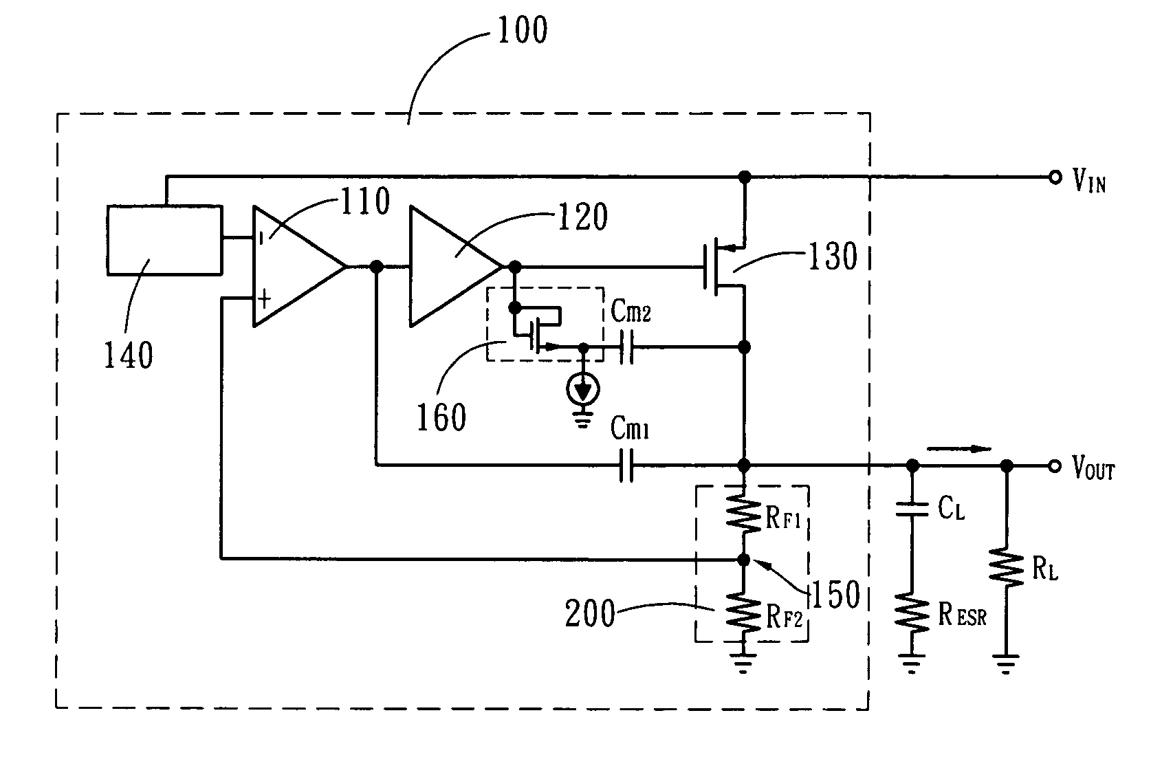
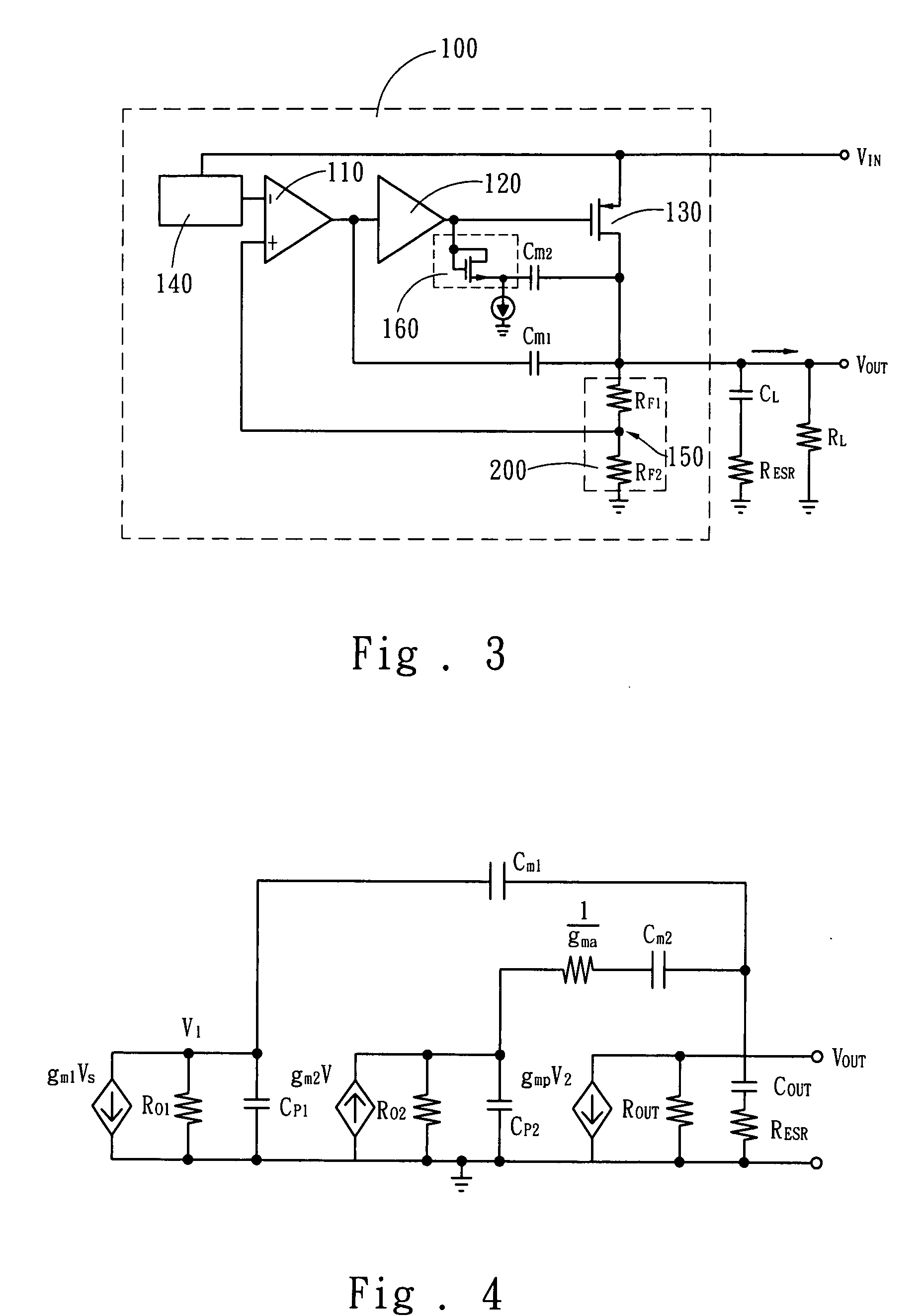
[0013]The primary objective of the present invention is to utilize nested Miller compensation and pole-splitting to move the dominant pole to the output of a first-stage amplifier. Such an approach does not need a big-size output capacitor, and the system can still have superior stability even under a zero-capacitance output capacitor. An active resistor is arranged in the feedback path of a Miller capacitor to increase the controllability of the damping factor, solve the problem of extensively using the output capacitor with a parasitic resistance, and solve the problem that a compromise must be made between the damping factor control and the system loop gain.
[0014]Another objective of the present invention is to utilize a capacitor-sharing technique to reduce the Miller capacitance of the entire system. Thus, the bandwidth can be extended, and the voltage stabilization can be accelerated.
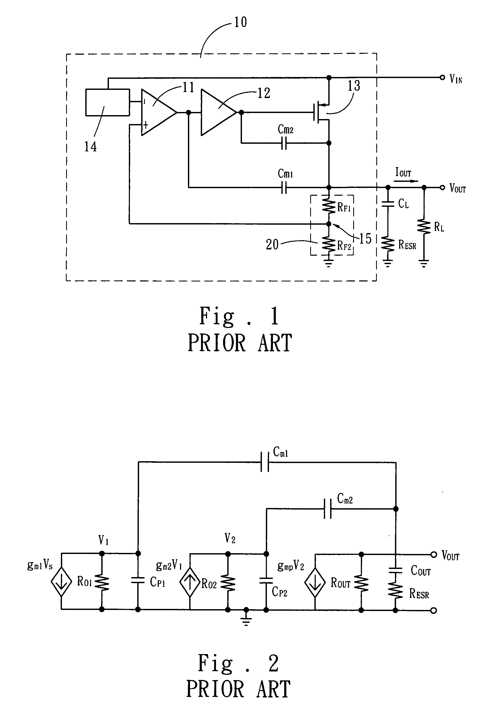
[0016]Based on nested Miller compensation, the present invention utilizes pole-splitting to move the dominant pole to the output of a first-stage amplifier. Thereby, the system does not need a big-size output capacitor, and the system can still have superior stability even under a zero-capacitance output capacitor, which benefits SOC (System-on-Chip) application, reduces circuit board area and decreases external elements. An insufficient damping factor will result in that frequency response has a surge appearing in the near-by of unit-gain frequency, and that the step response of the output voltage to the load current has ripples in the quasi-linear region; thus, the stabilization is decelerated. The damping factor varies with the output capacitance and the parasitic resistance of the output capacitor. Therefore, the present invention adds an active resistor to the feedback path of the Miller capacitor to increase the controllability of the damping factor, solve the problem of extensively using the output capacitor with a parasitic resistance, and solve the problem that a compromise must be made between the damping factor control and the system loop gain.
[0017]The LDO linear voltage regulator of the present invention further comprises a capacitor-sharing circuit. The capacitor-sharing circuit includes a shared capacitor. The capacitor-sharing circuit detects the current of the power transistor and switches the shared capacitor to connect in parallel with the first Miller compensation capacitor or the second Miller compensation capacitor. Thereby, the Miller capacitance required by the entire system is reduced, and the stabilization of output voltage is accelerated.
[0019]When the power transistor operates in the triode region, the shared capacitor is switched to connect in parallel with the first Miller compensation capacitor to create a greater Miller compensation capacitance to move the dominant pole to low frequency. In other words, when the load is light, the power transistor operates in the triode region, and the shared capacitor is switched to connect in parallel with the first Miller compensation capacitor to create a greater Miller compensation capacitance to move the dominant pole to low frequency so that the system can has a sufficient phase-angle margin.
[0020]When the power transistor operates in the saturation region, the shared capacitor is switched to connect in parallel with the second Miller compensation capacitor to create a greater Miller compensation capacitance to enhance the controllability of the damping factor. In other words, when the load current persistently increases and the power transistor operates in the saturation region, the shared capacitor is switched to connect in parallel with the second Miller compensation capacitor to create a greater Miller compensation capacitance to enhance the controllability of the damping factor. As there is smaller capacitance in the feedback path of the first Miller compensation capacitor at this time, the bandwidth can be extended when the load is heavy.

Problems solved by technology

An insufficient damping factor will result in that frequency response has a surge appearing in the near-by of unit-gain frequency, and that the step response of the output voltage to the load current has ripples in the quasi-linear region; thus, the stabilization is decelerated.

Method used


Image

  • Low dropout linear voltage regulator
  • Low dropout linear voltage regulator
  • Low dropout linear voltage regulator

Examples


Embodiment Construction

[0028]Below, the technical contents of the present invention are described in detail with the embodiments. It is to be noted that the embodiments are only to exemplify the present invention but not to limit the scope of the present invention.

[0029]Refer to FIG. 3 a diagram schematically showing that an active resistor is added to the feedback path of the Miller compensation capacitor. Based on the nested Miller compensation architecture, the low dropout (LDO) linear voltage regulator 100 of the present invention comprises: an input terminal VIN receiving input DC voltage; an output terminal VOUT outputting a stabilized output voltage; a first-stage amplifier 110; a second-stage amplifier 120 cascaded to the first-stage amplifier 110; and a power transistor 130 cascaded to the second-stage amplifier 120. The source of the power transistor 130 is coupled to the input terminal VIN, and the drain is coupled to the output terminal VOUT, and the gate is coupled to the output terminal of t...


PUM


Abstract

The present invention discloses an LDO (Low DropOut) linear voltage regulator, which is based on an NMC (Nested Miller Compensation) architecture and can be capacitor-free, wherein an active resistor is added to the feedback path of the Miller compensation capacitor to increase the controllability of the damping factor, solve the problem of extensively using the output capacitor with a parasitic resistance, and solve the problem that a compromise must be made between the damping factor control and the system loop gain. Further, the present invention utilizes a capacitor-sharing technique to reduce the Miller capacitance required by the entire system and accelerate the stabilization of output voltage without influencing stability.

Description

FIELD OF THE INVENTION[0001]The present invention relates to a low dropout linear voltage regulator, particularly to a low dropout linear voltage regulator adopting an active resistor and a capacitor-sharing technique to realize a capacitor-free feature.BACKGROUND OF THE INVENTION[0002]Due to the maturity of the communication market, the application of the relevant IC also persistently grows. With the prevalence of portable electronic products, such as mobile phones, battery runtime becomes very important. Thus, how to promote the efficiency and stability of batteries has been a challenge in the related field.[0003]Because of compactness, low noise and high conversion efficiency, the LDO (Low Dropout) linear voltage regulator has been the mainstream of small-power regulators and step-down transformers and has been widely used in portable electronic products and communication-related products.[0004]In the existing products / methods, three stages of amplifiers are usually adopted to in...

Claims


Application Information

Patent Timeline
IPC IPC(8): G05F1/10G05F1/00
CPCG05F1/575
Inventor HUANG, WEI-JEN
Owner SITRONIX TECH CORP
Learn More