
Ultra fast differential transimpedance digital amplifier for superconducting circuits

a digital amplifier and superconducting circuit technology, applied in logic circuits, electronic switching, pulse techniques, etc., can solve the problems of propagation delay, significant difference in the time when one device response is compared to another, and the limit of the number of squids that can be reliably fabricated for series connection, etc., to achieve less power, less on the chip, and better fabrication yield

Inactive Publication Date: 2009-01-01
HYPRES
View PDF3 Cites 27 Cited by
  • Summary
  • Abstract
  • Description
  • Claims
  • Application Information

AI Technical Summary

Benefits of technology

[0019]4. Modem semiconductor amplifiers used with the present invention have improved gain-bandwidth products, so they can achieve the required gain at higher speeds.
[0022]7. The invention utilizes many fewer Josephson junctions which therefore require less power and less on chip real restate. Further, the fewer Josephson junctions results in a better fabrication yield and reduce the complexity of circuit design and implementation.

Problems solved by technology

Another problem is that the characteristics of the SQUIDs in the stack should be very similar, if not identical.
The difficulty in making a large number of identical devices puts a limit on the number of SQUIDs that can be reliably fabricated for series connection.
Another problem is that of controlling the responses of SQUIDs in a stack so that they are all driven to the superconductive state or to the resistive state at the same time.
When a large number of SQUIDs are connected in series, this becomes very problematic since the control signals for setting or resetting the SQUIDs must be distributed over relatively large distances at the frequencies of interest.
At the operating frequencies of interest, very small differences in the length of a wire can cause a significant difference in the time when one device response is compared to another (i.e., propagation delay of the control signals).
Differences in the response time of the devices of a stack reduces the effective bandwidth of the circuit very significantly.
Further, the devices of the prior art have had a very limited bandwidth.

Method used


Image

  • Ultra fast differential transimpedance digital amplifier for superconducting circuits
  • Ultra fast differential transimpedance digital amplifier for superconducting circuits
  • Ultra fast differential transimpedance digital amplifier for superconducting circuits

Examples


Embodiment Construction

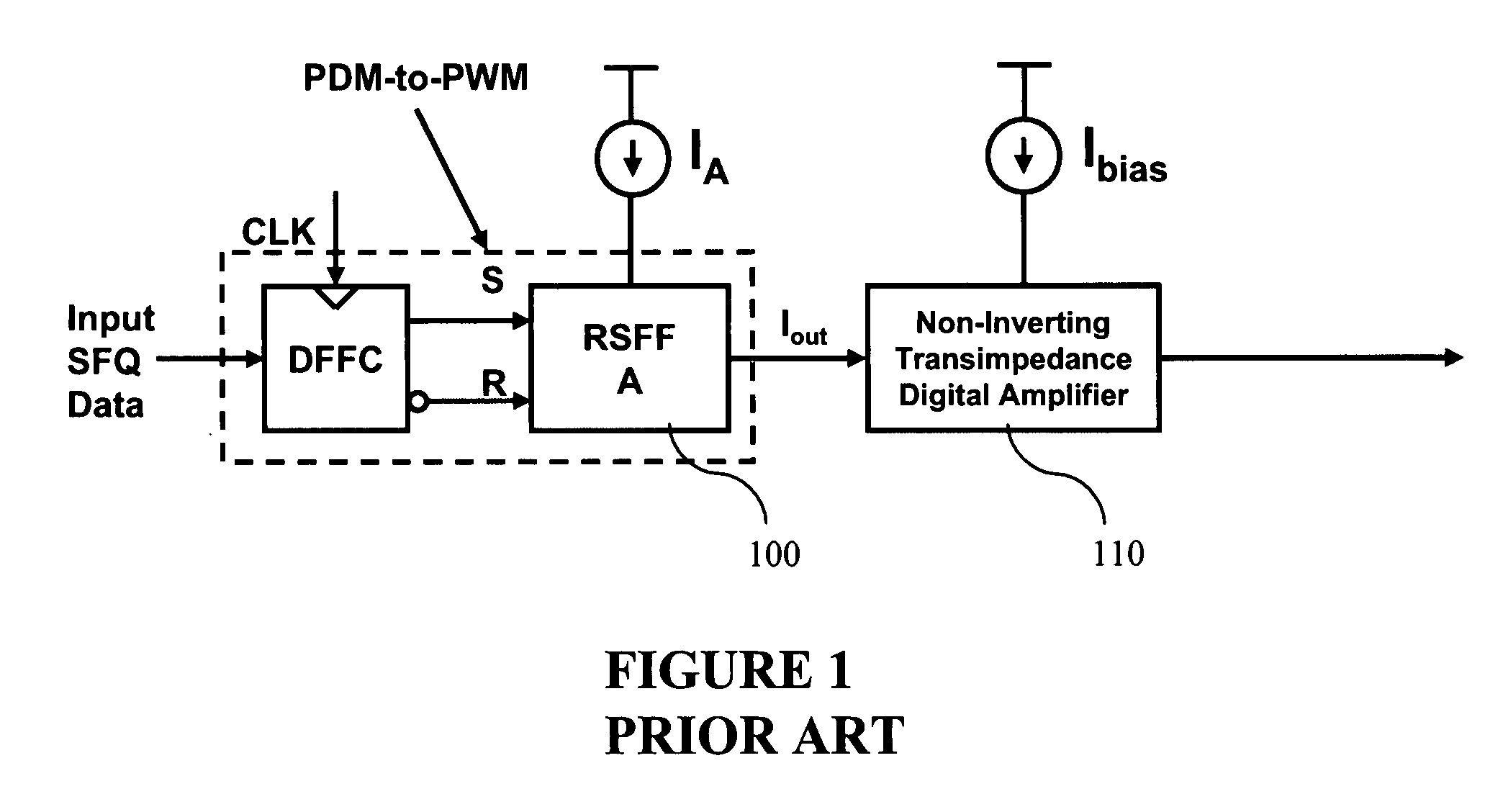
[0040]FIG. 1 is a block diagram of the non-inverting transimpedance digital amplifier which has been utilized in the prior art. Incoming data as received at the set (S) and reset (R) inputs of an RSFQ RS flip-flop 100 and the output pulse-width-modulated current are applied to the non-inverting transimpedance digital amplifier 110.

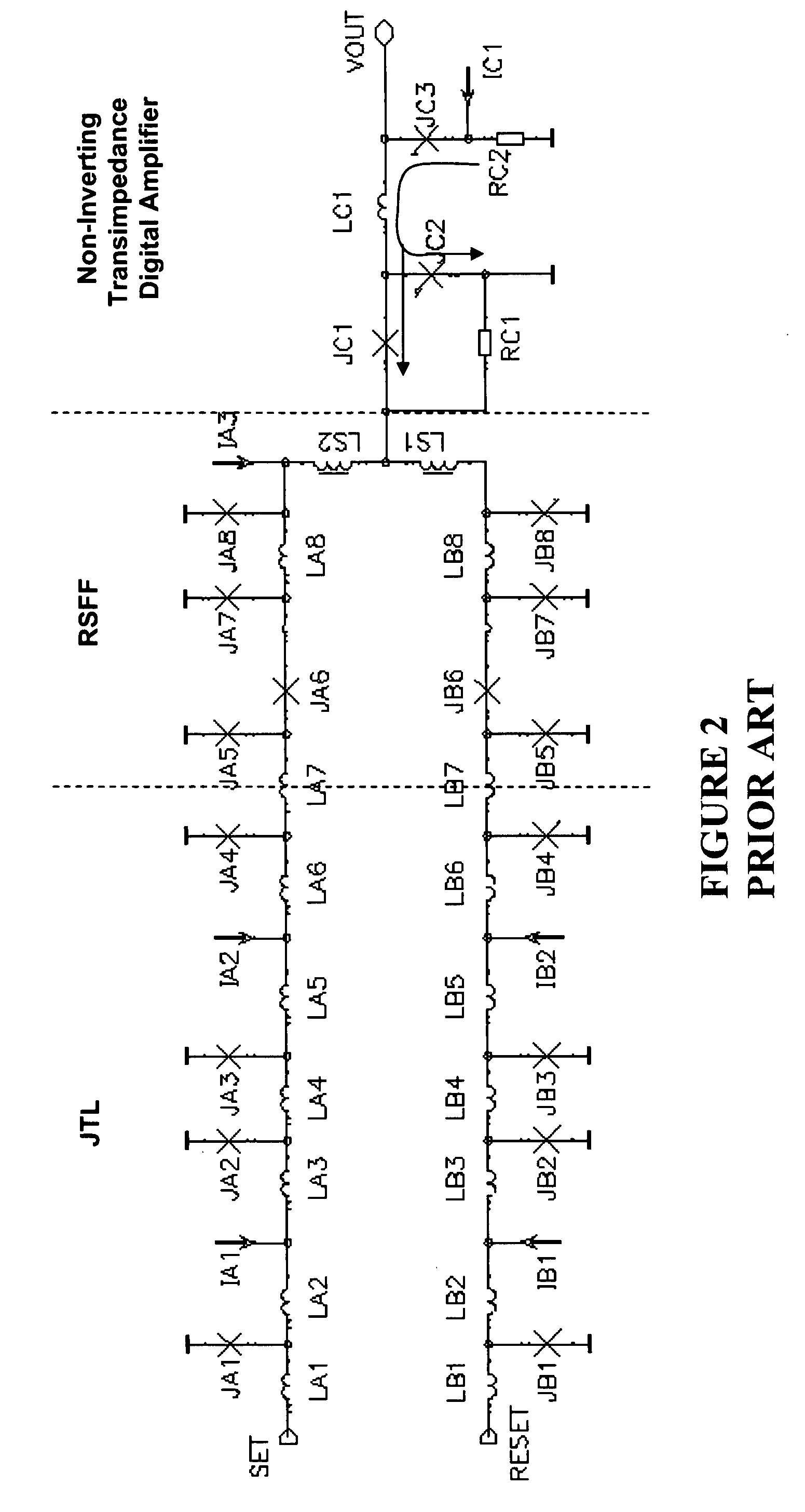
[0041]FIG. 2 is a schematic diagram of the prior art showing the interface between an RSFF and a non-inverting transimpedance digital amplifier shown in FIG. 1. Josephson transmission lines (JTL) are routinely used as interconnects between logic devices in RSFQ technology. Josephson junctions JA5-JA8 and JB5-JB8, LS1 and LS2 constitute an RS flip-flop which converts the pulse density modulated data stream received over the JTL into pulse-width-modulated current that drives the non-inverting transimpedance digital amplifier.

[0042]The PDM-to-PWM converter shown in FIG. 1 takes in SFQ (single flux quantum) pulses as control inputs (SET and RESET) and produces...


PUM


Abstract

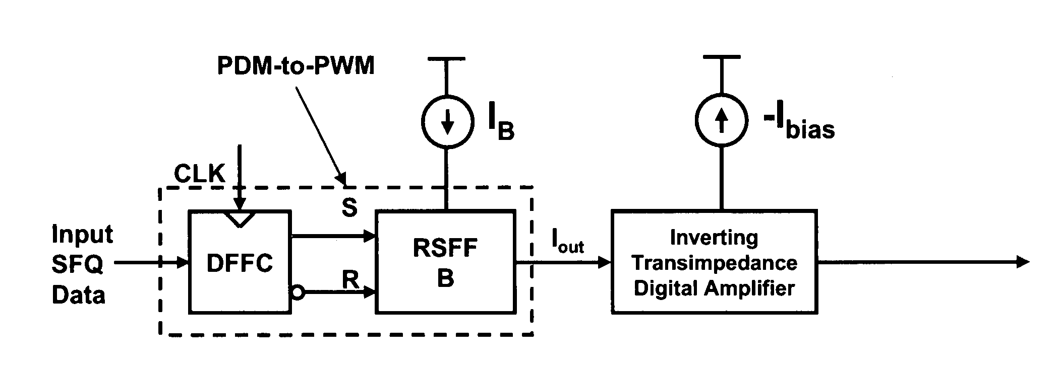
Supercooled electronics often use Rapid Single Flux Quantum (RSFQ) digital circuits. The output voltages from RSFQ devices are too low to be directly interfaced with semiconductor electronics, even if the semiconductor electronics are cooled. Techniques for directly interfacing RSFQ digital circuits with semiconductor electronics are disclosed using a novel inverting transimpedance digital amplifier in conjunction with a non-inverting transimpedance digital amplifier to create a differential transimpedance digital amplifier that permits direct interfacing between RSFQ and semiconductor electronics.

Description

[0001]The patent or application file contains at least one drawing executed in color. Copies of this patent or patent application publication with color drawing(s) will be provided by the Office upon request and payment of the necessary fee.BACKGROUND OF THE INVENTION [0002]1. Field of the Invention[0003]The Invention is directed to the field of superconducting circuits, and, more particularly, to the field of single flux quantum (SFQ) to DC drivers for interfacing Rapid Superconducting Single Flux Quantum (RSFQ) circuits to semiconductor circuits.[0004]2. Description of the Prior Art[0005]Ultrafast superconducting digital circuits are based on Josephson junctions integrated together according to RSFQ Logic (Rapid-single-flux-quantum), first proposed by K. Likharev and V. Semenov (1991). This is also a low-voltage technology, with fast voltage pulses 4 picoseconds wide and 0.5 mV in amplitude. In order to transmit the digital information to conventional semiconductor circuits, sever...

Claims


Application Information

Patent Timeline
IPC IPC(8): H03K19/195H03K17/92
CPCH03F19/00H03K11/00H03K19/1954H03K19/01H03K17/92
Inventor GUPTA, DEEPNARAYANINAMDAR, AMOL
Owner HYPRES
Learn More