Duplexer

a dual-layer, acoustic wave filter technology, applied in the direction of piezoelectric/electrostrictive/magnetostrictive devices, electrical apparatus, impedence networks, etc., can solve the problem of large ripple generation in a passband, insufficient power handling performance of longitudinally coupled resonator surface acoustic wave filters, and inability to achieve impedance matching. problem, to achieve the effect of easy impedance matching

Inactive Publication Date: 2009-01-01
MURATA MFG CO LTD
View PDF26 Cites 19 Cited by
  • Summary
  • Abstract
  • Description
  • Claims
  • Application Information

AI Technical Summary

Benefits of technology

[0016]To overcome the problems described above, preferred embodiments of the present invention provide a reliable balanced duplexer that includes a reception filter with a balanced-to-unbalanced conversion function and a transmission filter and is capable of easily achieving impedance matching when the balanced output of the reception filter is connected to the subsequent stage and preventing the reception filter from being damaged due to electric power supplied to the reception filter from the transmission filter.

Problems solved by technology

As a result, a large ripple is generated in a passband.
However, the longitudinally coupled resonator surface acoustic wave filter 1021 does not have sufficient power handling performance.
Accordingly, if the longitudinally coupled resonator surface acoustic wave filter 1021 is used in a duplexer, the longitudinally coupled resonator surface acoustic wave filter 1021 can be easily damaged by the electric power supplied thereto from a transmission filter.

Method used


Image

  • Duplexer
  • Duplexer
  • Duplexer

Examples


first preferred embodiment

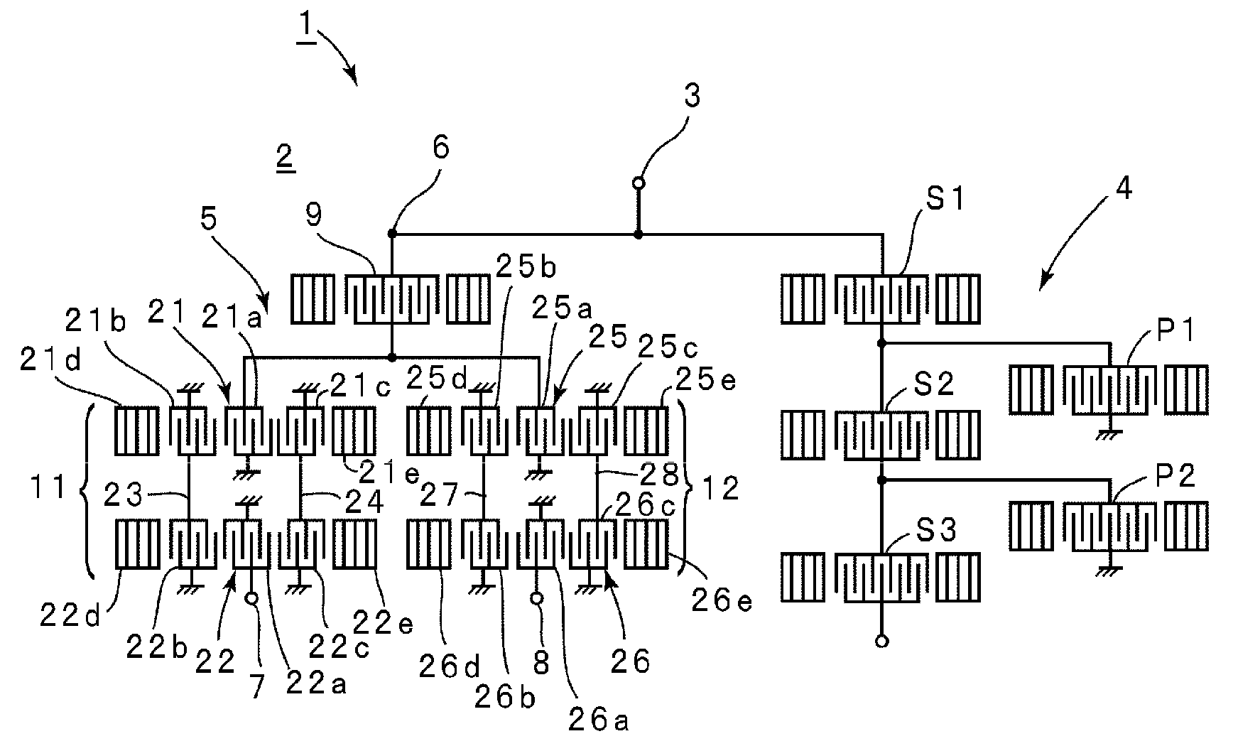
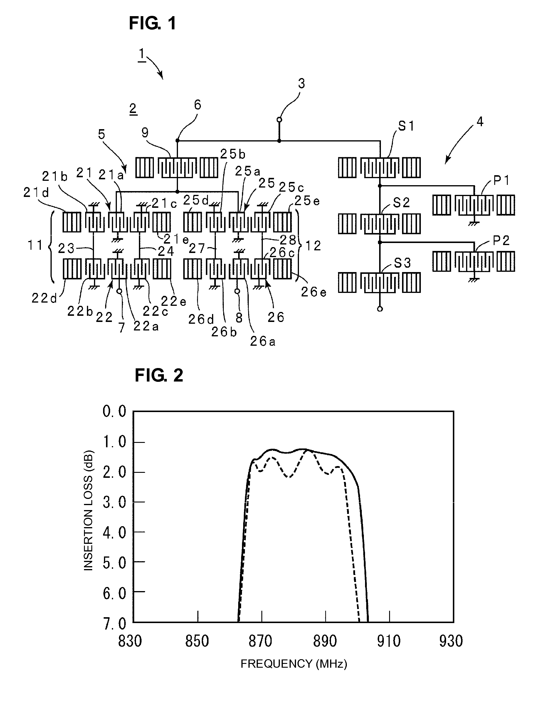
[0053]FIG. 1 is a schematic plan view describing a circuit configuration of a balanced duplexer according to the first preferred embodiment of the present invention. A duplexer 1 according to this preferred embodiment is preferably used in mobile telephones for CDMA800, for example. In CDMA800, a transmission frequency band is 824 to 849 MHz and a reception frequency band is 869 to 894 MHz.

[0054]In the balanced duplexer 1, an electrode structure illustrated in FIG. 1 is provided on a piezoelectric substrate 2. The piezoelectric substrate 2 is preferably a 42° Y-cut X-propagation LiTaO3 substrate, for example. The material of a piezoelectric substrate is not particularly limited. A LiTaO3 substrate having another cutting angle may be used. Alternatively, a piezoelectric substrate made of another piezoelectric material such as LiNbO3 may be used.

[0055]The balanced duplexer 1 includes an antenna terminal 3 connected to an antenna. The antenna terminal 3 is connected to a transmission f...

second preferred embodiment

[0075]FIG. 6 is a plan view illustrating an electrode structure of a duplexer according to a second preferred embodiment of the present invention. A duplexer 41 is substantially the same as the duplexer 1 according to the first preferred embodiment except for a reception filter 45.

[0076]In the reception filter 45, the one-port surface acoustic wave resonator 9 is connected to an input terminal 46, and is connected in parallel to a first filter element 51 and a second filter element 52. The first filter element 51 is a longitudinally coupled resonator surface acoustic wave filter element including a second IDT 51b, a first IDT 51a, and a third IDT 51c which are arranged in this order along a surface acoustic wave propagation direction. The second filter element 52 is also a longitudinally coupled resonator surface acoustic wave filter element including a second IDT 52b, a first IDT 52a, and a third IDT 52c which are arranged in this order along the surface acoustic wave propagation d...

third preferred embodiment

[0086]FIG. 9 is a schematic plan view illustrating an electrode structure of a duplexer according to the third embodiment of the present invention. A duplexer 81 is substantially the same as the duplexer 1 according to the first preferred embodiment except that a reception filter 82 is different from the reception filter 5.

[0087]The reception filter 82 includes an input terminal 83, the first reception output terminal 7, and the second reception output terminal 8. The input terminal 83 is connected to one end of the one-port surface acoustic wave resonator 9. The other end of the one-port surface acoustic wave resonator 9 is connected to a 5-IDT longitudinally coupled resonator filter element 84. The 5-IDT longitudinally coupled resonator filter element 84 includes a fourth IDT 84d, a second IDT 84b, a first IDT 84a, a third IDT 84c, and a fifth IDT 84e which are arranged in this order on a piezoelectric substrate along a surface acoustic wave propagation direction. A first reflecto...


PUM


Abstract

A duplexer includes a transmission filter having a ladder circuit configuration and a reception filter. The reception filter includes an input terminal connected to an antenna terminal, a first reception output terminal, and a second reception output terminal. A first filter element and a second filter element, each of which is a longitudinally coupled resonator filter element including a plurality of IDTs, are connected in parallel to the input terminal so that IDTs are connected to the input terminal. The first filter element the second filter element are connected to the first reception output terminal and the second reception output terminal, respectively.

Description

BACKGROUND OF THE INVENTION[0001]1. Field of the Invention[0002]The present invention relates to duplexers connected to an antenna terminal in a communication apparatus, such as a mobile telephone, and, more particularly, to a duplexer including a reception filter that utilizes an elastic wave filter device including a plurality of IDTs arranged on a piezoelectric substrate.[0003]2. Description of the Related Art[0004]Components included in an RF stage connected to an antenna in a mobile telephone have been combined to enable miniaturization of the mobile telephone. To achieve the miniaturization, a duplexer including an antenna terminal, a transmission band-pass filter, a reception band-pass filter, a transmission terminal, a reception terminal, and an output terminal is commonly used. Furthermore, a balanced duplexer has been developed in which a balanced band-pass filter having a balanced-to-unbalanced conversion function is used as a reception band-pass filter. Such a balanced d...

Claims


Application Information

Patent Timeline
Patent Type & Authority Applications(United States)
IPC IPC(8): H03H9/72
CPCH03H9/0057H03H9/0071H03H9/725H03H9/14588H03H9/14591H03H9/0085H03H9/64
Inventor TAKAMINE, YUICHI
Owner MURATA MFG CO LTD
Why Eureka
Try Eureka