
High efficiency digital transmitter incorporating switching power supply and linear power amplifier

a digital transmitter and linear power amplifier technology, applied in the field of data communication, can solve the problems of high switching efficiency, am-am and am-pm distortion, and high switching noise, and achieve the effects of improving power efficiency of a transmitter, reducing bandwidth envelope, and improving power efficiency

Inactive Publication Date: 2009-01-01
TEXAS INSTR INC
View PDF12 Cites 394 Cited by
  • Summary
  • Abstract
  • Description
  • Claims
  • Application Information

AI Technical Summary

Benefits of technology

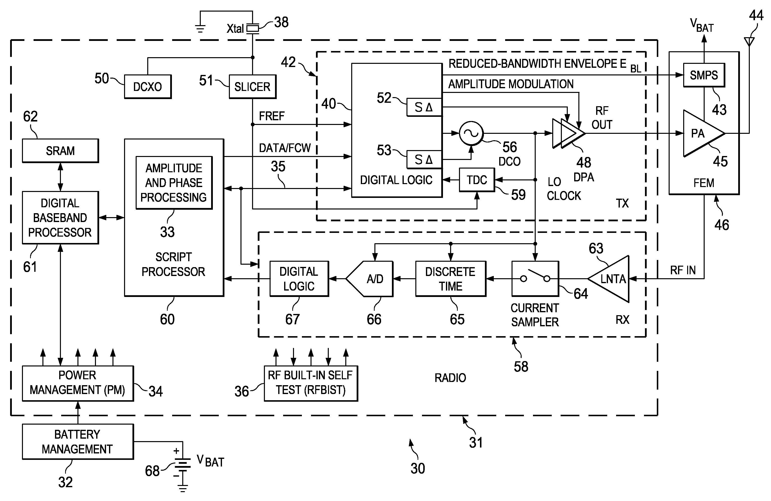
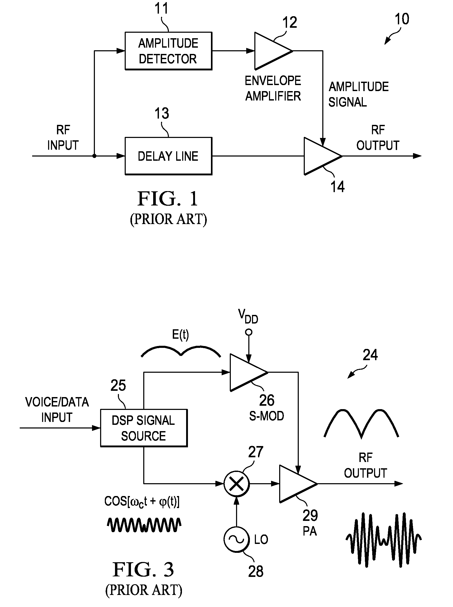
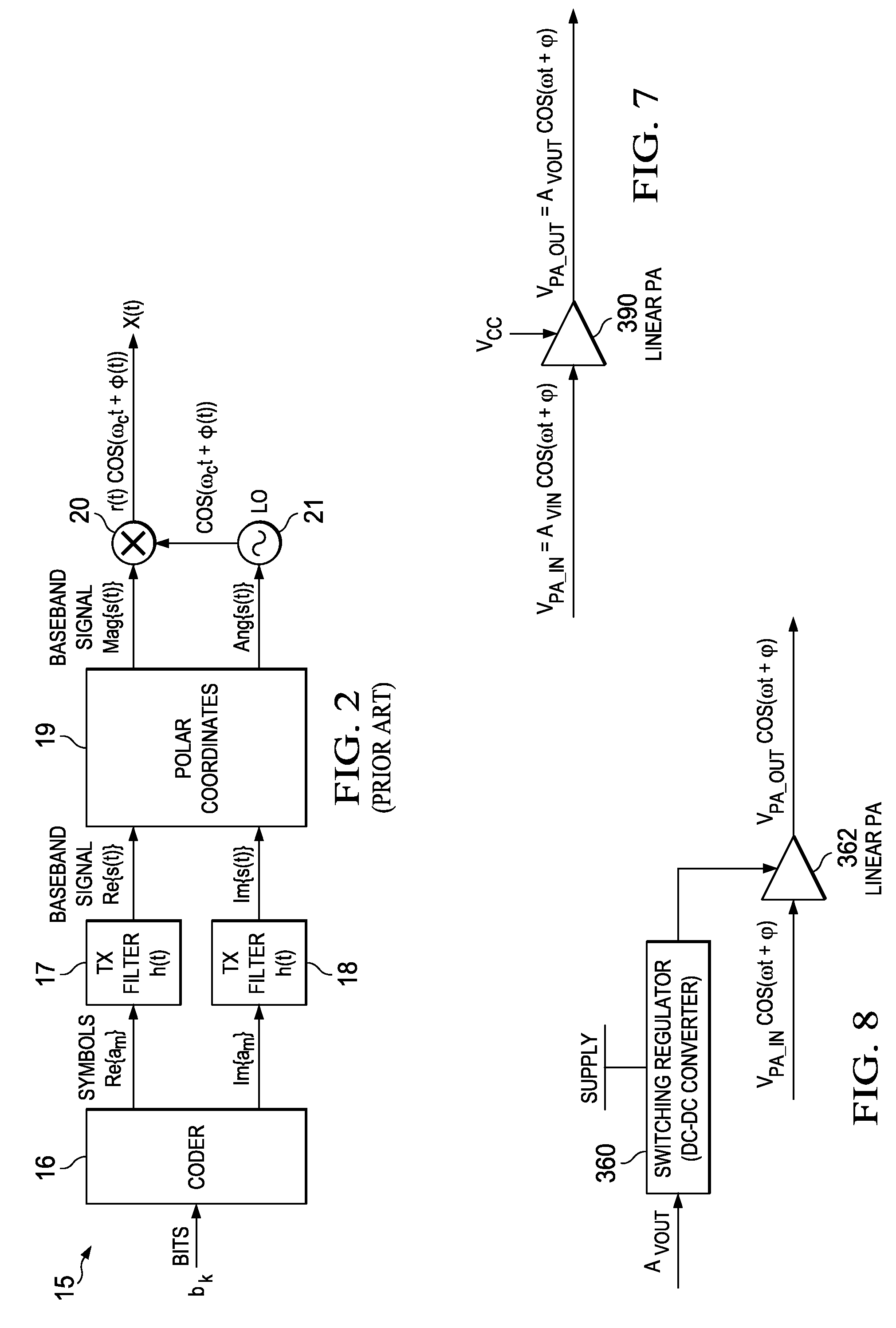
The present invention is a novel apparatus and method for improving the power efficiency of a digital transmitter for non-constant-amplitude modulation schemes. The invention leverages a switched mode power supply (SMPS) that supplies high current to the power amplifier (PA) while using a lower switching rate to achieve high efficiency. The invention compensates for distortions in the PA by using predistortion of the digital amplitude modulating signal. The invention can be implemented in any system that requires a wide-bandwidth amplitude signal and a linear power amplifier, such as RF transmitters or digital radio processors. The invention achieves improved power efficiency, reduced bandwidth requirements, and reduced noise in the transmitter.

Problems solved by technology

The drawbacks include primarily the switching noise created by the SMPS and the degraded efficiency at high rates of switching, which is needed to accommodate wide bandwidth input signals.
This results in varying amounts of AM-AM and AM-PM distortions in the power amplifier (PA).
In one embodiment, predistortion is not needed at all, either due to the sufficient headroom that is always maintained by the band-limited envelope signal modulating the PA supply (at the cost of compromised efficiency), or through the use of a closed-loop scheme wherein the output amplitude and phase are constantly monitored and error signals are generated therefrom to compensate for distortions that are experienced in them.

Method used


Image

  • High efficiency digital transmitter incorporating switching power supply and linear power amplifier
  • High efficiency digital transmitter incorporating switching power supply and linear power amplifier
  • High efficiency digital transmitter incorporating switching power supply and linear power amplifier

Examples


first embodiment

[0112]In a first embodiment, sufficient headroom is maintained in the linear power amplifier such that the reduced-bandwidth envelope signal is used alone (i.e. without any predistortion) to improve power efficiency. In this embodiment, the linear power amplifier is configured to have sufficient headroom to minimize any saturation / distortion.

second embodiment

[0113]In a second embodiment, the reduced-bandwidth envelope signal is used in combination with some type of pre-compensation. The compensation is used to compensate for supply-dependent distortions suffered in the power amplifier as a result of the headroom occasionally being too low to maintain perfect linearity (particularly around the highest peaks in the envelope). Compensation comprises amplitude and phase predistortions that are applied to the PA input signal. The predistortions may be implemented either (1) using a look up table (LUT) populated with predistortion correction values; or (2) a polynomial or equivalent that is calculated to determine the appropriate predistortion to apply for a particular input.

[0114]In the second embodiment, the digital signal processing portion of the mechanism of the invention accounts for the supply-dependent distortions suffered in the power amplifier and compensates for them by predistorting the PA input signal in a feed-forward manner. Th...

third embodiment

[0116]In a third embodiment, a form of feedback, based on continuous monitoring and detection of the power-amplifier's output signal, is used to adjust the envelope and phase of the internal modulation, and possibly also the envelope used for the supply modulation (i.e. the signal applied at the input to the regulator). Although an efficient negative feedback system may substitute for the feed-forward predistortion altogether, in the presence of reasonably accurate feed-forward predistortion, the errors for the feedback system would be reduced and the finite suppression offered by the feedback system for these errors will be able to meet the requirements of the particular wireless standard with less effort (e.g., reduced bandwidth in the closed-loop control system). In this case, circuitry, computation and energy efficiency may be optimized as the effort is distributed between the two paths.

[0117]The end result for the system is that the desired RF performance is obtained for the tr...


PUM


Abstract

A novel apparatus and method of improving the power efficiency of a digital transmitter for non-constant-amplitude modulation schemes. The power efficiency improvement mechanism of the invention leverages the high efficiency of a switched-mode power supply (SMPS) that supplies the high DC current to the transmitter's power amplifier, while compensating for its limitations using predistortion. The predistortion may be achieved using any suitable technique such as digital signal processing, hardware techniques, etc. A switched mode power supply (i.e. switching regulator) is used to provide a slow form (i.e. reduced bandwidth) of envelope tracking (based on a narrower bandwidth distorted version of the envelope waveform) such that the switching regulator can use a lower switching rate corresponding to the lower bandwidth, thereby obtaining high efficiency in the switching regulator. The resulting AM-AM and AM-PM distortions in the power amplifier are compensated through predistortion of the digital amplitude modulating signal which dictates the envelope at the PA input. Similarly, the phase modulation is also compensated prior to the PA, such that once it undergoes the distortion in the PA, the end result is sufficiently close to the desired phase.

Description

REFERENCE TO PRIORITY APPLICATION[0001]This application claims priority to U.S. Provisional Application Ser. No. 60 / 946,545, filed Jun. 27, 2007, entitled “Power Efficient Digital Transmitter”, incorporated herein by reference in its entirety.FIELD OF THE INVENTION[0002]The present invention relates to the field of data communications and more particularly relates to a power efficient digital transmitter that incorporates a linear amplifier and switched mode power supply.BACKGROUND OF THE INVENTION[0003]In the rapidly expanding market of wireless mobile devices, the demand for more power efficient RF transceivers is ever increasing. The efficiency of the final stage power amplification in transmitters has a very significant impact on the overall power efficiency and on the battery life of the device. High efficiency power amplifiers (PAs) are thus critical in portable battery-operated wireless communications due to the fact that they typically dominate the overall power consumption ...

Claims


Application Information

Patent Timeline
Patent Type & Authority Applications(United States)
IPC IPC(8): H04B1/04
CPCH03F1/0211H03F1/3247H04B1/0483H03F3/24H03F1/3282
Inventor ELIEZER, OREN E.FEYGIN, GENNADYMEHTA, JAIMIN
Owner TEXAS INSTR INC
Learn More