
Method of recycling spent flue gas denitration catalyst and method of determining washing time of spent flue gas denitration catalyst

a technology of denitration catalyst and flue gas, which is applied in the direction of other chemical processes, instruments, separation processes, etc., can solve the problems of not revealing any method of calculating a washing time, requiring a large amount of manpower and equipment, and taking a long time to carry out analysis, etc., to achieve low cost, low cost, and low cost

Active Publication Date: 2009-01-01
KOREA ELECTRIC POWER CORP +3
View PDF3 Cites 11 Cited by
  • Summary
  • Abstract
  • Description
  • Claims
  • Application Information

AI Technical Summary

Benefits of technology

The present invention provides a method for determining the optimal time to wash a spent flue gas denitration catalyst with less manpower and time, and a method for recycling the catalyst at low cost and high efficiency using the determined washing time. The method involves physically removing solids and poisoning substances from the catalyst, and washing it with a washing liquid for a specific time period determined by measuring the hydrogen ion concentration of the washing liquid. The recycling method involves drying the catalyst after washing. The invention also provides a better understanding of the properties and recycling methods of flue gas denitration catalysts.

Problems solved by technology

However, the above patent application does not disclose any method of calculating a washing time.
As above, the conventional methods for calculating an optimal washing time analyze the poisoning substances contained in the washing liquid quantitatively using an analyzer such as an inductively coupled plasma atomic emission spectrometer; however, the convention methods using such analysis equipment have some drawbacks in that they requires a considerable amount of manpower and equipment and it takes a lot of time to carry out the analysis.

Method used

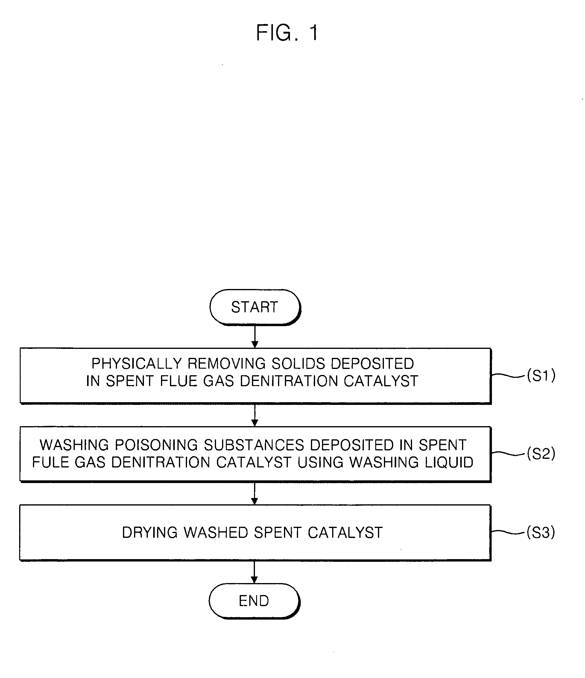
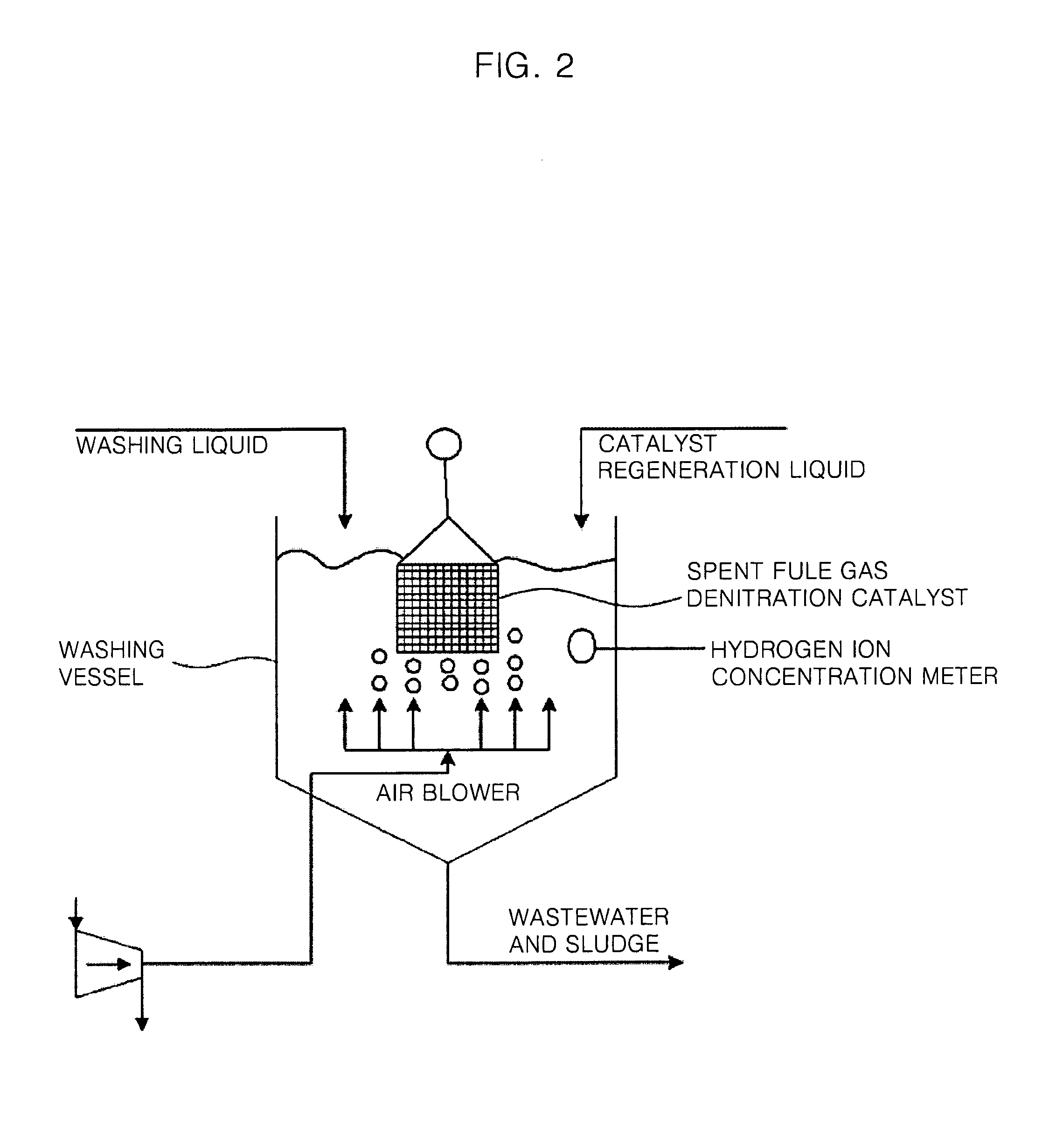

Image

  • Method of recycling spent flue gas denitration catalyst and method of determining washing time of spent flue gas denitration catalyst
  • Method of recycling spent flue gas denitration catalyst and method of determining washing time of spent flue gas denitration catalyst
  • Method of recycling spent flue gas denitration catalyst and method of determining washing time of spent flue gas denitration catalyst

Examples


experimental example 1

Change in Hydrogen Ion Concentration According to Washing Time

[0044]The spent catalyst used in this Experimental Example was one that was used in flue gas denitration equipment of a thermal power plant for a long period of time such as 1,300 hours and had a denitrification efficiency lowered to about 58% at a temperature of 350° C. The above catalyst was a commercially available catalyst having a 20 cell-per-square-inch (CPSI) honeycomb structure and prepared by supporting V2O5 and WO3 on a titanium dioxide carrier. The test catalyst was made into a granule having a size of 30 mm in length, 30 mm in width and 45 mm in height and immersed in distilled water of 1,000 ml so that the poisoning substances were eluted for 60 minutes. Here, the hydrogen ion concentrations with the passage of time were measured and shown in FIG. 3. It can be seen from FIG. 3 that the hydrogen ion concentration becomes nearly constant after 10 minutes.

experimental example 2

Elution Amounts of Poisoning Substances According to Washing Time

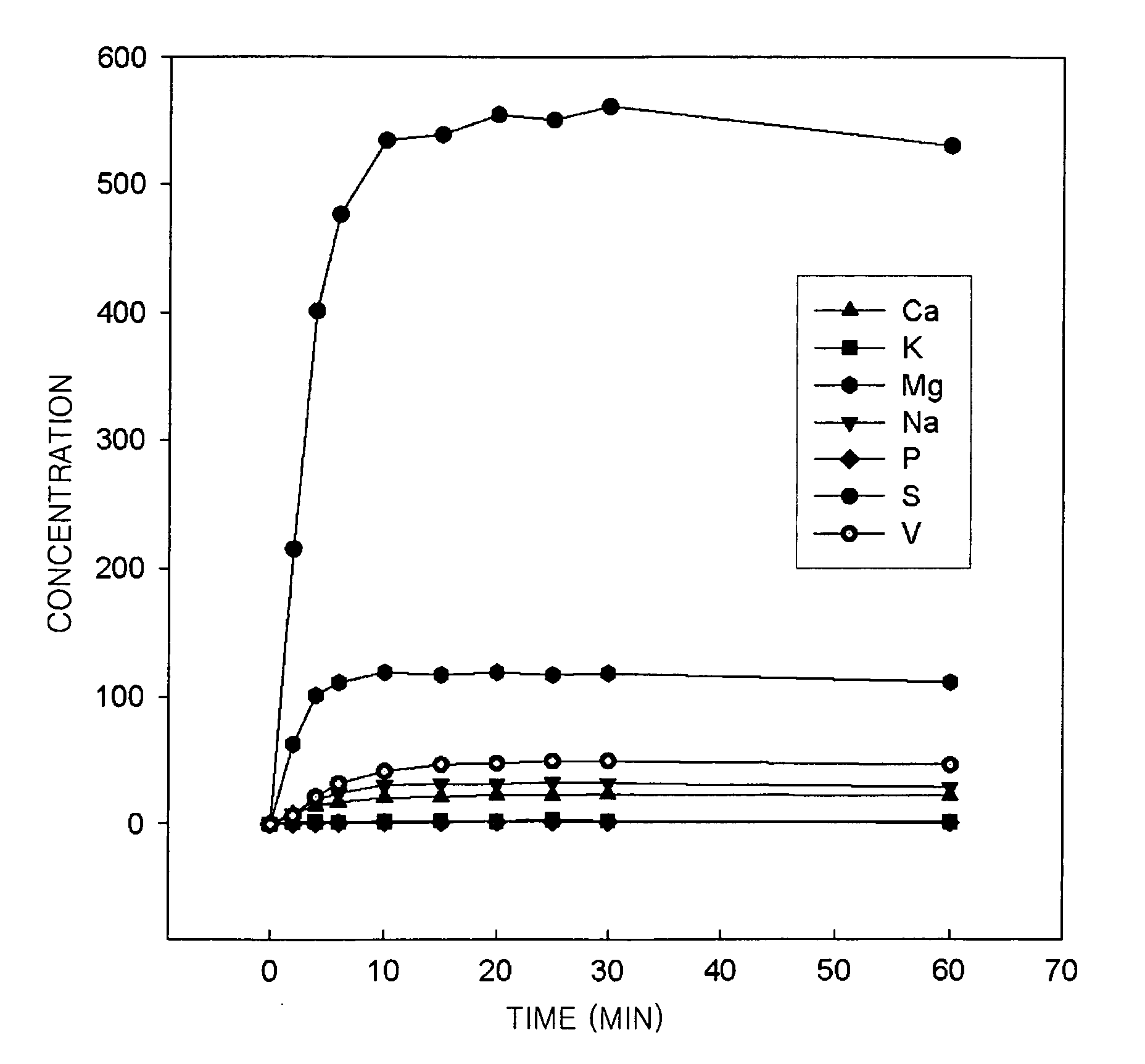
[0045]The elution amounts of the poisoning substances such as Ca, K, Mg, Na, P, S and V according to the washing time in the catalyst and washing liquid, the same as those in Experimental Example 1, were analyzed using an inductively coupled plasma atomic emission spectrometer. FIG. 4 shows the elution amounts of the poisoning substances according to the washing time. It can be seen from FIG. 4 that the elution amounts of most poisoning substances become constant within about 10 minutes from the beginning of the washing process. These results are the same as those obtained from the measurement of the hydrogen ion concentrations according to the washing time. Accordingly, it can be understood that the time when the poisoning substrates are eluted, i.e., the washing time, can be calculated through the measurement of the hydrogen ion concentration in real time without using complicated equipment such as the inductively co...

experimental example 3

Denitrification Rates of Catalyst According to Washing Time

[0046]Under the same conditions as Experimental Examples 1 and 2, the denitrification rates of the catalyst were measured by varying the washing time. In this Experimental Example, the conditions for the measurement of the denitrification rates are shown in the following Table 1:

TABLE 1Reaction temperature400° C.Space velocity20,000 / hrMolar ratio of ammonia / nitrogen oxide1.0Nitrogen oxide500 ppmSulfur oxide500 ppmOxygen5%

[0047]The denitrification rates according to the washing time obtained from the above measurement are shown in the following Table 2. It can be understood from Table 2 that the regeneration efficiency of the catalyst is increased until 10 minutes in the washing process and then there is no change in the regeneration efficiency although the washing time is increased.

TABLE 2Washing timeDenitrification rate 0 minutes58.0% 4 minutes66.2%10 minutes78.3%20 minutes79.0%30 minutes78.5%60 minutes78.6%

[0048]It can be ...


PUM

PropertyMeasurementUnit
temperatureaaaaaaaaaa

Abstract

The present invention provides a method of recycling a spent flue gas denitration catalyst and a method of determining a washing time of the spent flue gas denitration catalyst. The method of recycling the spent flue gas denitration catalyst includes physically removing solids deposited in the spent flue gas denitration catalyst, removing poisoning substances deposited in the spent flue gas denitration catalyst by washing the spent flue gas denitration catalyst with a washing liquid for a washing time determined by measuring the hydrogen ion concentration of the washing liquid and drying the resulting spent flue gas denitration catalyst.

Description

RELATED APPLICATIONS[0001]This application claims priority and is an accurate translation of Korean Patent Application No. 10-2007-0063237, filed Jun. 26, 2007, the entire disclosure of which is incorporated herein by reference.BACKGROUND[0002]1. Field of the Invention[0003]This invention relates to a method of recycling a spent flue gas denitration (de-NOx) catalyst and a method of determining a washing time of the spent flue gas denitration catalyst and, more particularly, to a method of recycling a spent flue gas denitration catalyst, of which activity has been lowered, using a washing liquid in a selective catalytic reduction (SCR) process for removing nitrogen oxides (NOx) contained in flue gas, and a method of determining a washing time using the washing liquid.[0004]2. Related Art[0005]A method of removing nitrogen oxides that is most widely used in thermal power stations, incinerators, industrial boilers, etc. is a selective catalytic reduction (SCR) technique, in which the ...

Claims


Application Information

Patent Timeline
Patent Type & Authority Applications(United States)
IPC IPC(8): B01J38/48B01J38/64G01N33/00
CPCB01J21/20B01J23/92B01J38/48Y10T436/22B01J38/62Y10S502/514Y10S502/515B01J38/60B01J23/90
Inventor LEE, IN-YOUNGLEE, JUNG-BINKIM, DONG-WHA
Owner KOREA ELECTRIC POWER CORP
Learn More