Method to control mask profile for read sensor definition

a sensor and mask profile technology, applied in the field of magnetoresitive sensor manufacturing, can solve the problems of preventing clean, accurate sensor definition, non-uniform deposition of layers, and poor trackwidth, and achieve the effect of eliminating any shadowing effects, reducing the rate at which the photoresist mask material is removed, and not diminishing the precision of sensor definition

Inactive Publication Date: 2009-01-08
HITACHI GLOBAL STORAGE TECH NETHERLANDS BV
View PDF9 Cites 13 Cited by
  • Summary
  • Abstract
  • Description
  • Claims
  • Application Information

AI Technical Summary

Benefits of technology

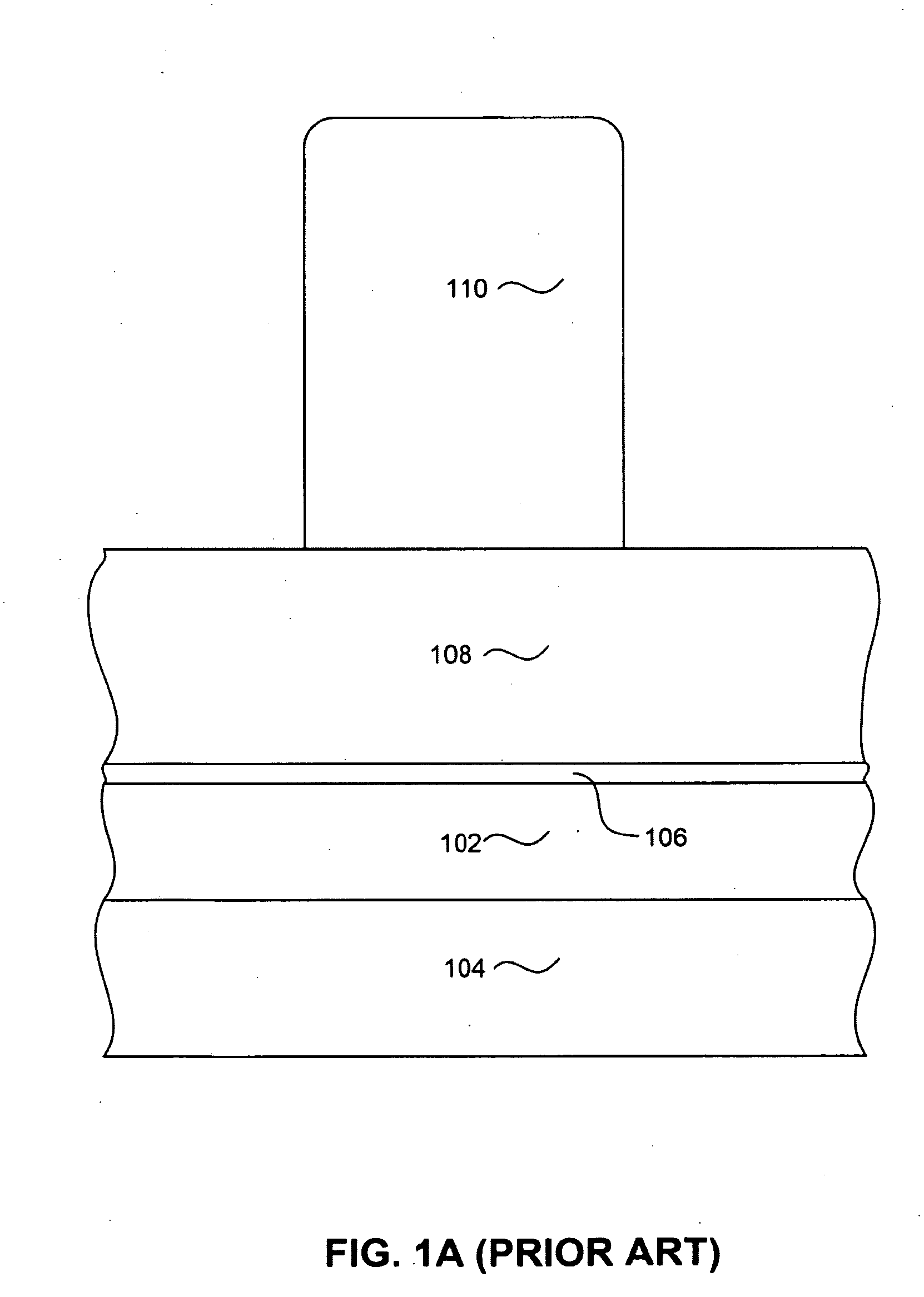
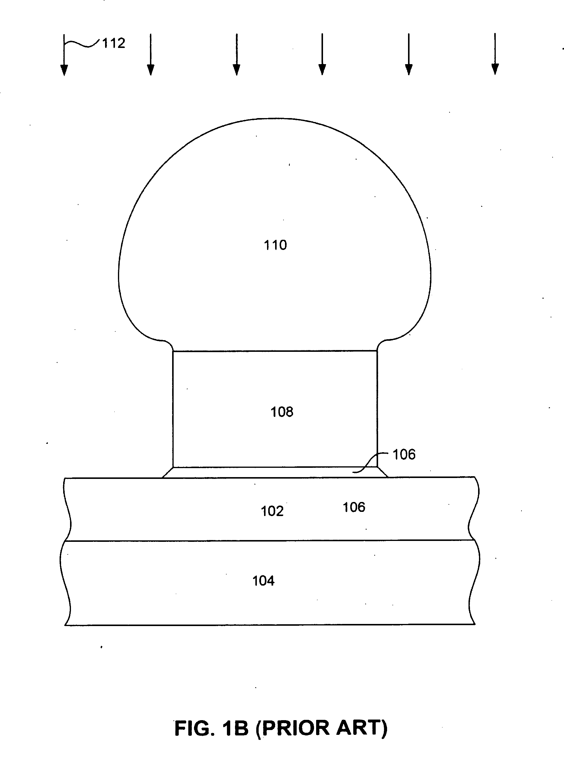
[0018]The present invention provides a method for manufacturing a sensor in which the precision of the sensor definition is not diminished by shadowing effects. The method involves depositing a series of sensor layers as full film layers onto a substrate. A CMP stop layer can then be deposited over the sensor layers, followed by an antireflective coating layer (ARC). Then a photosensitive mask is formed over the ion mill resistant mask layer. A reactive ion etch is then performed to remove exposed portions of the underlying ion mill resistant mask and the CMP stop. The reactive ion etch is performed while applying a platen power greater than a 70 Watts (W), and preferably of at least 100 Watts (W). More preferably, the reactive ion etch is performed while applying a platen power of around 300 W. The application of this higher platen power increases the physical component of material removal, increasing the rate at which the photoresist mask material is removed, thereby eliminating the formation a bulbous or mushroom shaped mask layer and eliminating any shadowing effects resulting therefrom.
[0021]The inventive method of constructing a sensor advantageously avoids the formation of a bulbous or mushroom shaped mask layer, thereby preventing the shadowing effects ordinarily associated with the use of a photoresisist mask formed over an ion mill resistant mask.

Problems solved by technology

A sloping sensor side wall results in a poorly defined trackwidth.
Unfortunately, the bulbous mask structure prevents clean, accurate sensor definition.
In addition, the bulbous mask shape result in non-uniform deposition of layers such as hard bias layers and lead layers.

Method used


Image

  • Method to control mask profile for read sensor definition
  • Method to control mask profile for read sensor definition
  • Method to control mask profile for read sensor definition

Examples


Embodiment Construction

[0030]The following description is of the best embodiments presently contemplated for carrying out this invention. This description is made for the purpose of illustrating the general principles of this invention and is not meant to limit the inventive concepts claimed herein.

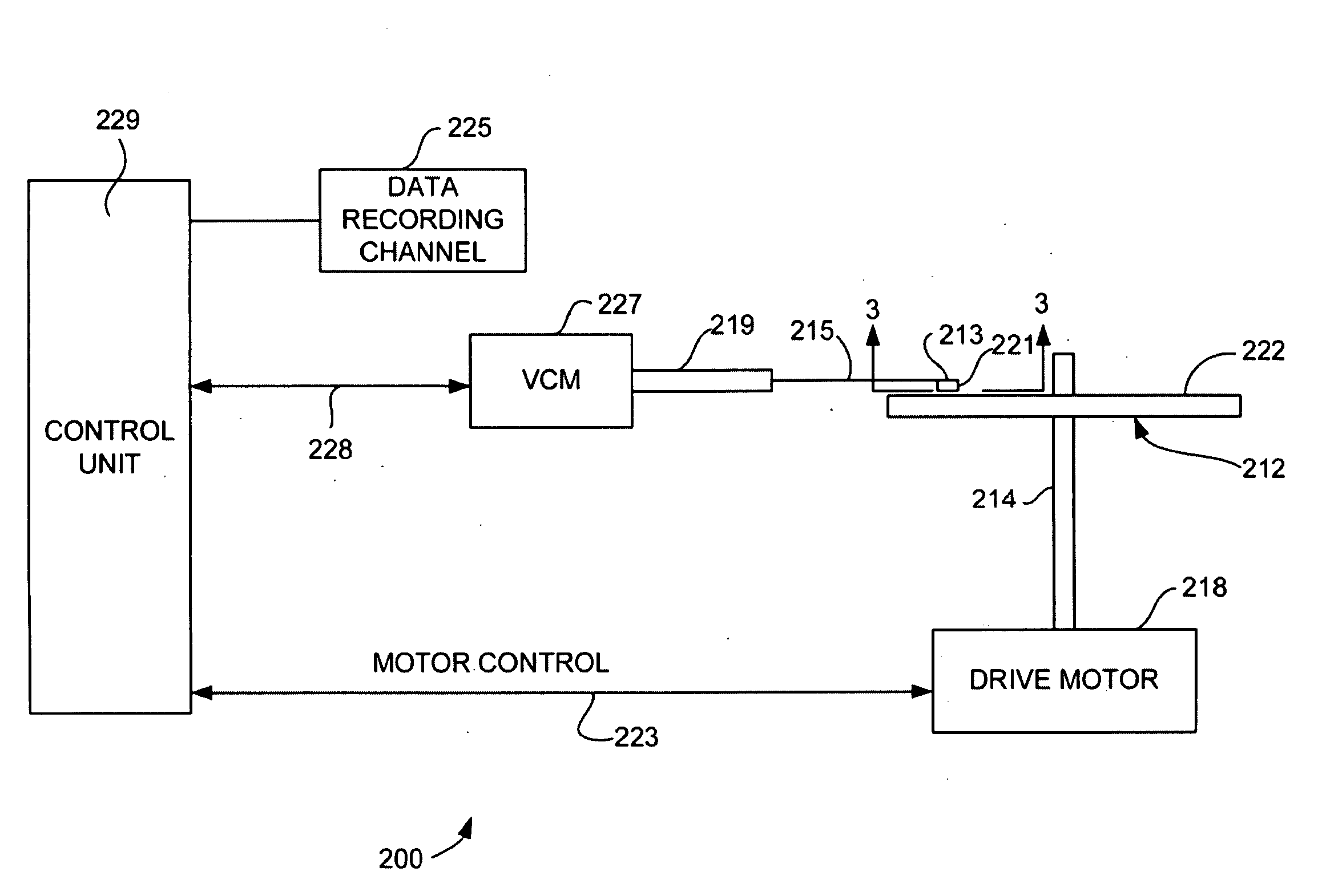
[0031]Referring now to FIG. 2, there is shown a disk drive 200 embodying this invention. As shown in FIG. 2, at least one rotatable magnetic disk 212 is supported on a spindle 214 and rotated by a disk drive motor 218. The magnetic recording on each disk is in the form of annular patterns of concentric data tracks (not shown) on the magnetic disk 212.

[0032]At least one slider 213 is positioned near the magnetic disk 212, each slider 213 supporting one or more magnetic head assemblies 221. As the magnetic disk rotates, slider 213 moves radially in and out over the disk surface 222 so that the magnetic head assembly 221 may access different tracks of the magnetic disk where desired data are written. Each slider 2...


PUM

PropertyMeasurementUnit
poweraaaaaaaaaa
platen poweraaaaaaaaaa

Abstract

A method for constructing a magnetoresistive sensor that avoids shadowing effects of a mask structure during sensor definition. The method includes the use of an antireflective coating (ARC) and a photosensitive mask deposited there over. The photosensitive mask is formed to cover a desired sensor area, leaving non-sensor areas exposed. A reactive ion etch is performed to transfer the pattern of the photosensitive mask onto the underlying ARC layer. The reactive ion etch (RIE) is performed with a relatively high amount of platen power. The higher platen power increases ion bombardment of the wafer, thereby increasing the physical (ie mechanical) component of material removal relative to the chemical component. This increase in the physical component of material removal result in an increased rate of removal of the photosensitive mask material relative to the ion mill resistant mask. This avoids the formation of a bulbous or mushroom shaped photoresist mask and therefore, avoids shadowing effects during subsequent manufacturing processes.

Description

RELATED APPLICATIONS[0001]This Application is a Continuation Application of copending U.S. patent application Ser. No. 11 / 046,421, entitled METHOD TO CONTROL MASK PROFILE FOR READ SENSOR DEFINITION filed on Jan. 28, 2005 to common inventors, which is incorporated herein by reference in its entirety as if fully set forth herein.[0002]This Application is also a Continuation In Part Application of copending U.S. patent application Ser. No. 11 / 035,771, entitled MAGNETORESISTIVE SENSOR HAVING A NOVEL JUNCTION STRUCTURE FRO IMPROVED TRACK WIDTH DEFINITION AND PINNED LAYER STABILITY, filed on Jan. 14, 2005 to common inventors, which is incorporated herein by reference as if fully set forth herein.FIELD OF THE INVENTION[0003]The present invention relates to the manufacture of magnetoresitive sensors and more particularly to a method for accurately defining the side walls and track width of a magnetoresistive sensor.BACKGROUND OF THE INVENTION[0004]The heart of a computer is an assembly that...

Claims


Application Information

Patent Timeline
Patent Type & Authority Applications(United States)
IPC IPC(8): G11B5/127
CPCB82Y10/00B82Y25/00G11B5/3163G11B5/3903G11B5/398G11B2005/3996Y10T29/49021Y10T29/49044Y10T29/49046Y10T29/49043Y10T29/49048Y10T29/49052Y10T29/49041Y10T29/49032
Inventor CONTRERAS, RICHARD JULEFELDBAUM, MICHAELPINARBASI, MUSTAFA MICHAEL
Owner HITACHI GLOBAL STORAGE TECH NETHERLANDS BV
Why Eureka
Try Eureka