Plasma ignition system

a technology of ignition system and plasma, which is applied in the direction of ignition control, other installations, machines/engines, etc., can solve the problems of high frequency electromagnetic wave noise, ignition system is expected to be applied, and severe ignition condition, and achieves excellent effect of preventing an emission and being convenient to install

Active Publication Date: 2009-01-08
DENSO CORP
View PDF19 Cites 23 Cited by
  • Summary
  • Abstract
  • Description
  • Claims
  • Application Information

AI Technical Summary

Benefits of technology

[0011]The present invention addresses the above disadvantages. Thus, it is an objective of the present invention to provide a plasma ignition system, which is easi

Problems solved by technology

Recently, from a standpoint of environmental protection, lean mixture combustion or supercharged mixture combustion, for example, is required in an internal combustion engine to reduce emissions in combustion exhaust gas or to improve fuel mileage, so that an ignition condition is becoming severe.
Thus, such a plasma ignition system is expected to be applied to an ignition system in an internal combustion engine of difficult ignitionability in which lean mixture combustion or supercharged mixture combustion, for example, is performed.
Since the above passing of high current is periodically repeated according to rotation of the engine, an electromagnetic wave noise of high frequency is generated.
Malfunction of the electronic control un

Method used


Image

  • Plasma ignition system
  • Plasma ignition system
  • Plasma ignition system

Examples


first embodiment

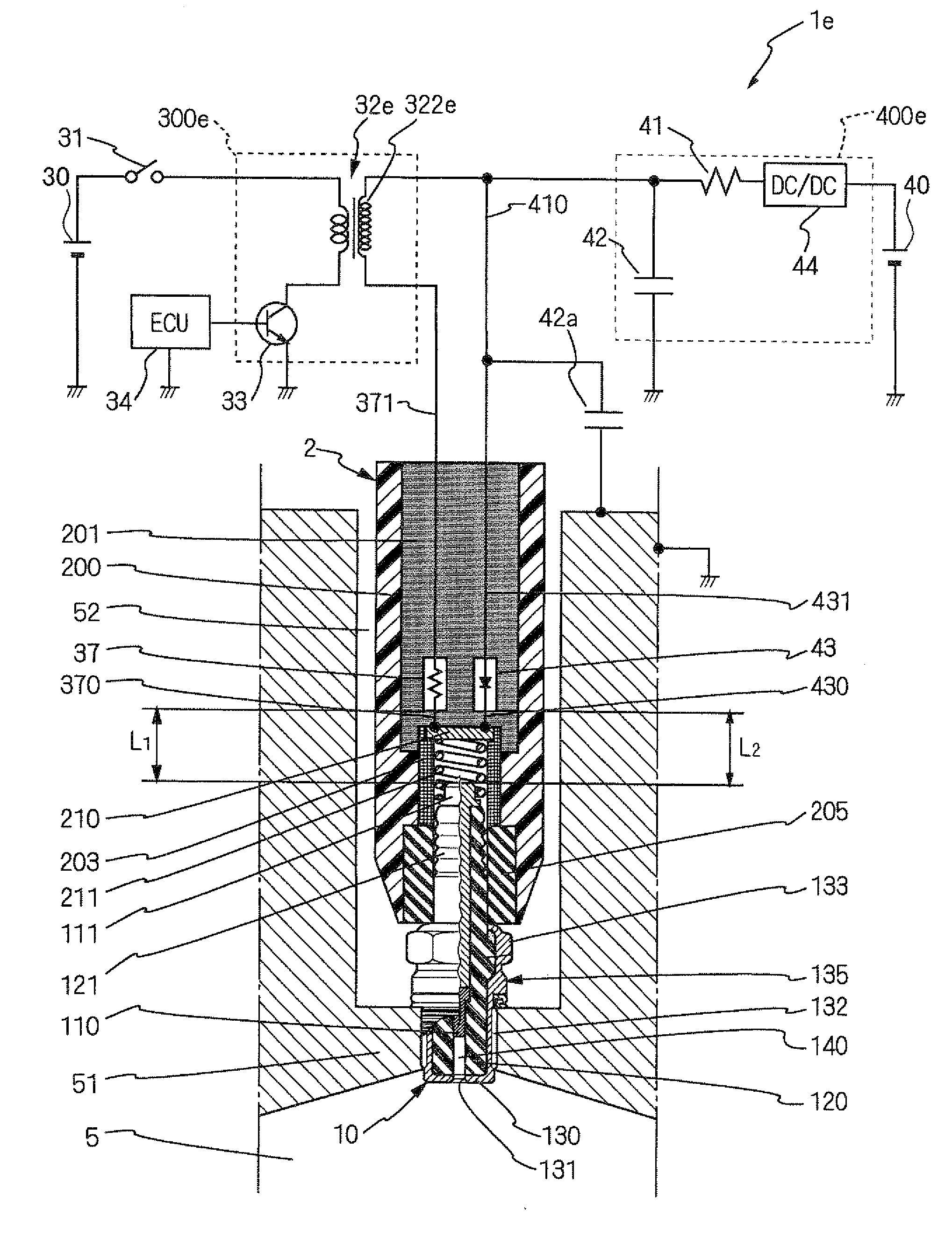
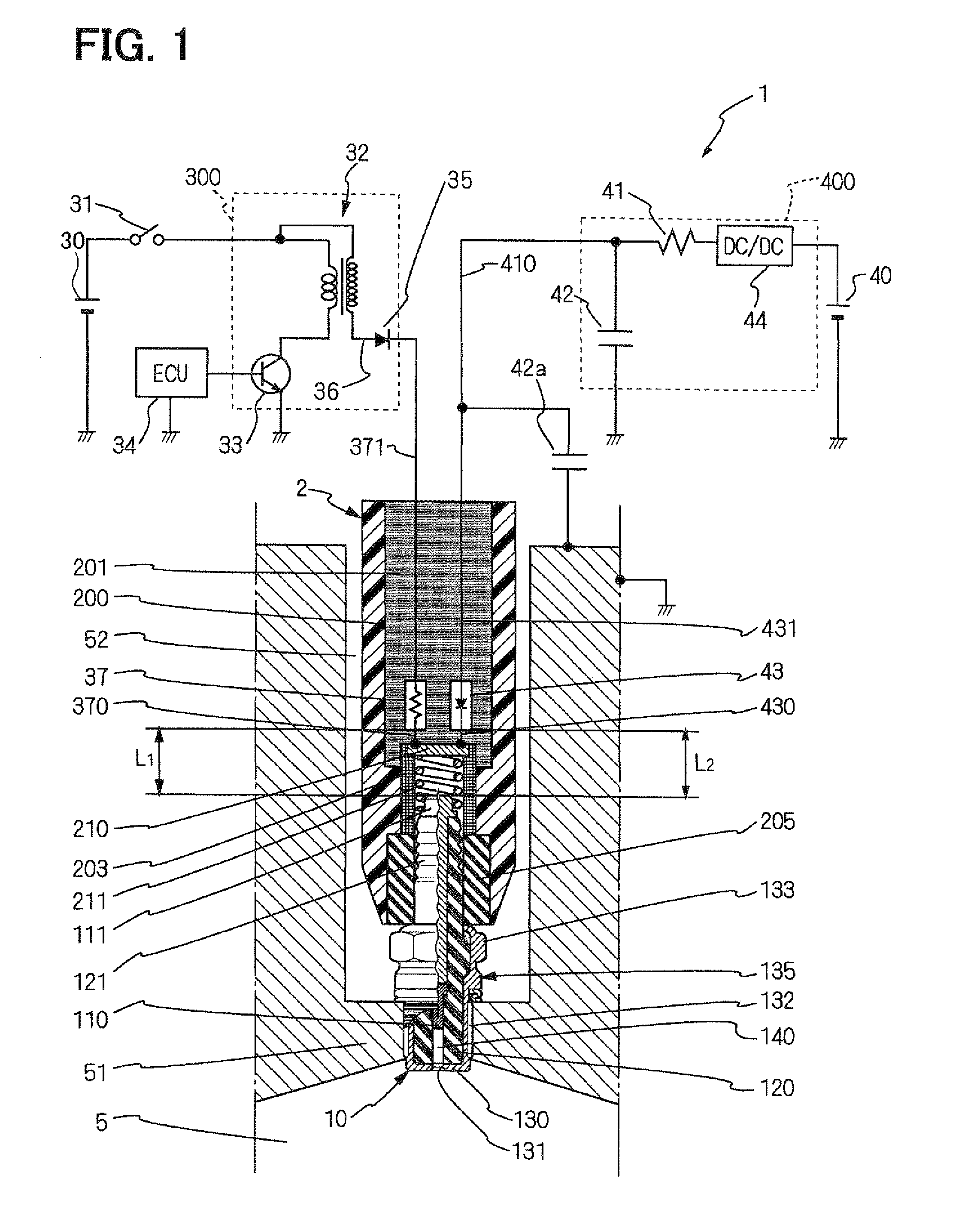
[0050] the electromagnetic-wave noise, which is generated in the discharge power source circuit 300 and is transmitted through the distribution line from the discharge power source circuit 300 to the spark plug 10, is converted into heat by the resistance element 37 and is absorbed. Because an electric current passing from the discharge power source circuit 300 is restricted by the resistance element 37, and a variation of the current becomes small, the generation of the electromagnetic-wave noise is restricted. Electric discharge is a high frequency phenomenon that is generated instantaneously. Thus, the electromagnetic-wave noise generated due to the current variation generated at the time of electric discharge is promptly absorbed by positioning the resistance element 37 near the electric discharge part, so that the electromagnetic-wave noise reduction effect is enhanced. The variation of electric current is made small by the resistance element 37, and thus a variation of a magne...

fourth embodiment

[0055]The plasma generation capacitor 42b is charged by the power source 40b, and releases the high current to the plasma ignition plug 10 at the time of its electric discharge. In the fourth embodiment, the plasma generation capacitor 42b is grounded to the engine block 51, and functions also as a capacitor for electromagnetic wave noise reduction, which bypasses the electromagnetic wave noise generated at the time of the electric discharge to the engine block 51.

[0056]A resistance wire 41 is connected between the power source 40 and a contact point 411. A primary side of the ignition coil 32, the plasma generation capacitor 42b, and the rectifying device 43, which are connected in parallel at the contact point 411, are connected by a resistance-less line.

[0057]With reference to FIG. 7, a circuit configuration of the plasma ignition system 1b of the fourth embodiment of the invention, and an advantageous effect of the invention are explained in full detail. The plasma ignition syst...

sixth embodiment

[0076]In order to prevent leakage of an electromagnetic wave noise to the outside of the receiving portion 2d, it is necessary that the electromagnetic wave noise should not be applied between a plasma generation capacitor 42 and the third terminal part 240. In the sixth embodiment, the plasma generation capacitor 42 is distanced from a rectifying device 35 that rectifies a discharge current and its wiring 36d, in which the electromagnetic wave noise is generated, and the second terminal part 230 is separated from the third terminal part 240. It turns out that generation of the electromagnetic wave noise is further reduced by disposing the plasma generation capacitor 42 near the third terminal 240. Furthermore, by placing the plasma generation capacitor 42 away from the second terminal part 230, the leakage of a high voltage for electric discharge applied to the second terminal part 230 to the plasma generation capacitor 42 is prevented. In addition, the element receiving portion 2d...


PUM


Abstract

A plasma ignition system includes an ignition plug attached to an engine and having a center electrode, a ground electrode, and a discharge space, a discharge power source circuit, a plasma generation power source circuit, a resistance element between the discharge power source circuit and the center electrode, a rectifying device between the plasma generation power source circuit and the center electrode, and an element receiving portion in a periphery of the center electrode. The plug puts gas in the discharge space into a plasma state to ignite a fuel/air mixture in the engine, as a result of application of high voltage to the plug by the discharge power source circuit and supply of high current to the plug by the plasma generation power source circuit. The resistance element and the rectifying device are placed in the receiving portion.

Description

CROSS REFERENCE TO RELATED APPLICATION[0001]This application is based on and incorporates herein by reference Japanese Patent Application No. 2007-173745 filed on Jul. 2, 2007 and Japanese Patent Application No. 2008-120919 filed on May 7, 2008.BACKGROUND OF THE INVENTION[0002]1. Field of the Invention[0003]The present invention relates to measures to prevent leakage of electromagnetic wave noise in a plasma ignition system, which is used for ignition in an internal combustion engine.[0004]2 Description of Related Art[0005]Recently, from a standpoint of environmental protection, lean mixture combustion or supercharged mixture combustion, for example, is required in an internal combustion engine to reduce emissions in combustion exhaust gas or to improve fuel mileage, so that an ignition condition is becoming severe. Accordingly, an ignition system, in which stable ignitionability is achieved, is required in an engine of poor ignitionability.[0006]In the case of ignition of the engin...

Claims


Application Information

Patent Timeline
IPC IPC(8): F02P3/06
CPCF02P23/04F02P9/007
Inventor KATO, HIDEYUKIYOSHINAGA, TOHRUSHIBATA, MASAMICHI
Owner DENSO CORP
Why Eureka
Try Eureka