
Robust solution for mitigating eccentricity in a rotary sensor apparatus

Inactive Publication Date: 2009-01-08
HONEYWELL INT INC
View PDF14 Cites 10 Cited by
  • Summary
  • Abstract
  • Description
  • Claims
  • Application Information

AI Technical Summary

Benefits of technology

[0015]The aforementioned aspects and other objectives and advantages can now be achieved as described herein. An improved rotary sensor apparatus and method thereof are disclosed, which includes a hollow cylindrical magnet design implemented to drive a parallel field magnetic sensor based on Hall / AMR principals. The variation in the X and Y axes can be reduced by, for example, 20% compared with the use of a solid magnet. The configuration and methodology described herein can improve repeatability, while reducing linearity and correlation errors associated the rotary sensor. For tilts of ±3 degrees, for example, the error can be reduced to 50% compared to the use of a solid magnet. The use of the hollow cylindrical magnet described herein represents a major advantage and increase in repeatability and accuracy. The polarity of rotary sensor can be identified by locating a chamber on the magnet ID at the “north pole” of the cylindrical magnet. The centrality between the cylindrical magnet and the chip is less critical. A pole in the rotor, however, can provide a good support for fixing the magnet within the rotor, over which the magnet can be either heat stacked or bonded.
[0016]The disclosed concept can be utilized for implementing a rotary position sensor with less error after lifecycle while improving the yield during production. A platform electronics and magnet combination can be configured for serving user requirements (range of measurement and other specifications) quickly. The novelty of the design includes improved linearity and robustness in vibration, and part-to-part variations during manufacturing of the rotary sensor, thereby increasing yield in production and improved reliability in lifecycle as design is less affected by wear and tear due to mechanical vibrations.

Problems solved by technology

Eccentricity or dislocation of the magnet position may occur due to harsh operating conditions such as, for example, wear and tear in the lifecycle, which is most common in automotive applications.
Due to this issue, achieving the same repeatability every time when the sensor is tested is questionable.
Because of the increase in error, the correlation error in dual o / p sensor may be increased.
Due to an increase in the B field components error, the linearity and correlation errors, in the case of dual o / p sensors, can increase.
Polarity identification during the assembly of the sensor calls for a tedious process that increases product costs.

Method used


Image

  • Robust solution for mitigating eccentricity in a rotary sensor apparatus
  • Robust solution for mitigating eccentricity in a rotary sensor apparatus
  • Robust solution for mitigating eccentricity in a rotary sensor apparatus

Examples


Embodiment Construction

[0024]The particular values and configurations discussed in these non-limiting examples can be varied and are cited merely to illustrate at least one embodiment and are not intended to limit the scope thereof.

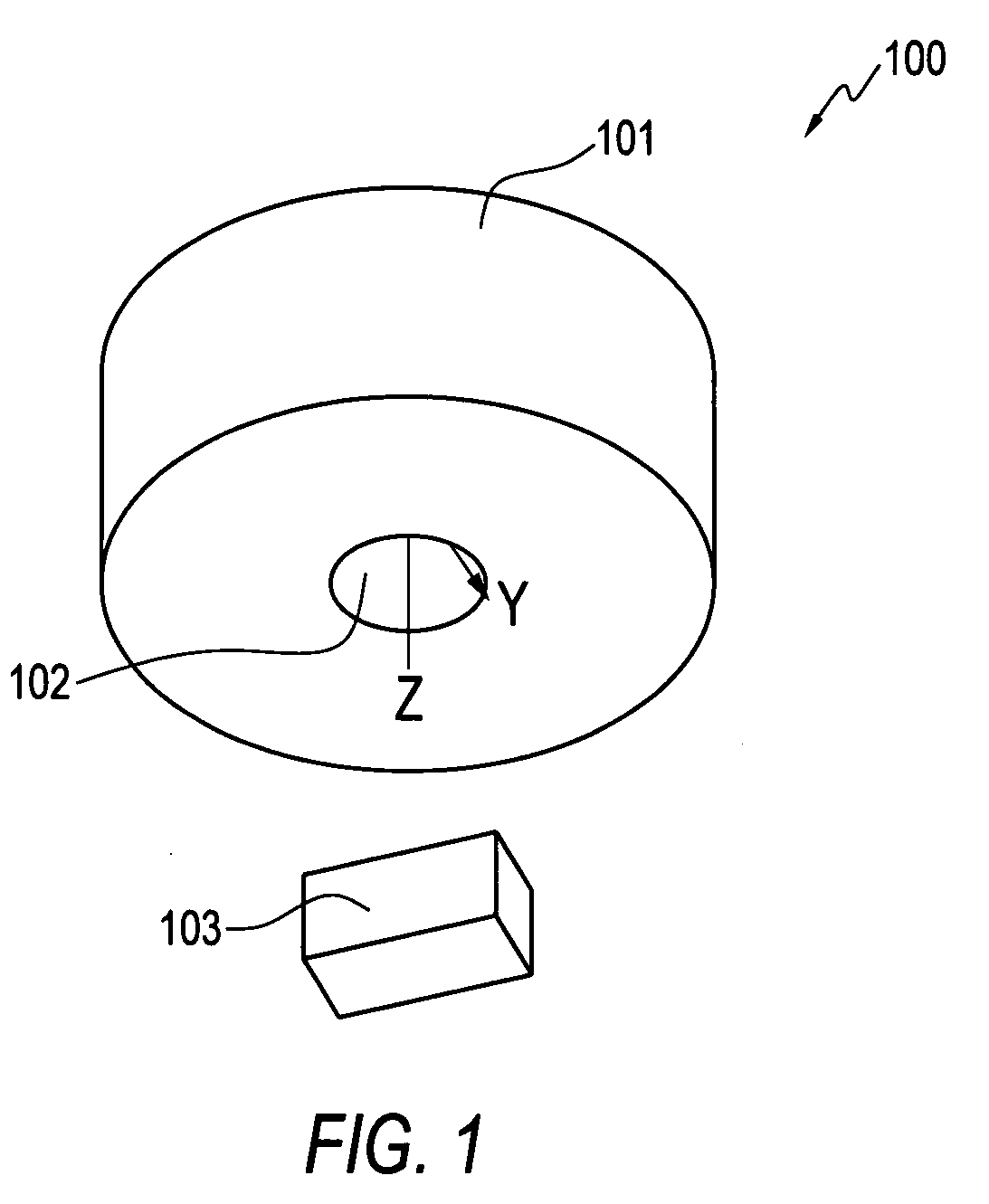
[0025]Referring to FIG. 1, a perspective view of a hollow cylindrical magnet 100 is illustrated, as a robust solution for eccentricity issues in rotary sensor applications, in accordance with a preferred embodiment. The hollow cylindrical magnet 100 includes a magnetic cylindrical surface (shell) 101 with a hollow cavity 102. A rotary sensing element such as, for example, a AMR / Hall chip 103 can be arranged in a position below the cylindrical magnet 101. The rotary sensing element or Hall / AMR chip 103 comprises a sensing element (not shown in figure) fitted in a hybrid integrated circuit.

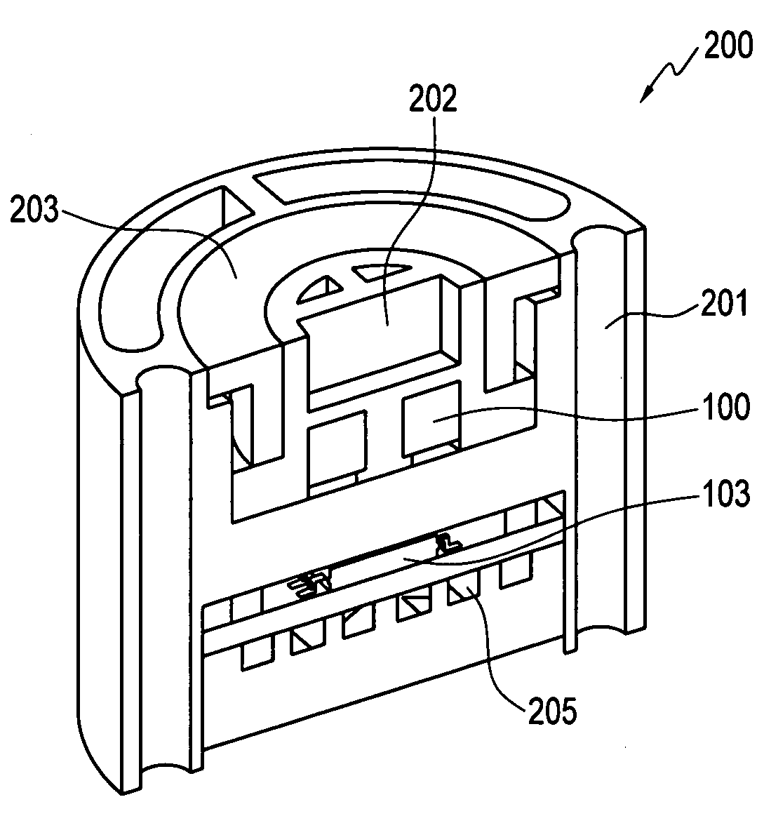
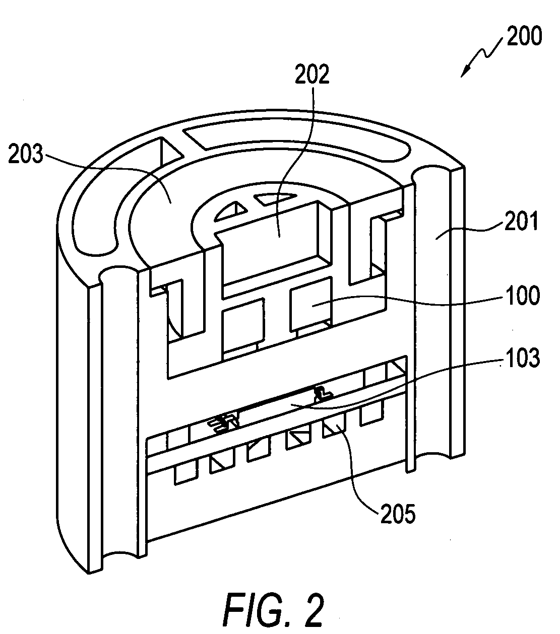
[0026]FIG. 2 illustrates a cross-sectional view of a rotary position sensor apparatus 200 apparatus equipped with the hollow cylindrical magnet 100 depicted in FIG. 1, in accordance with a pref...


PUM


Abstract

A robust solution for eccentricity issues in 360 degree rotary sensor application utilizing a hollow cylindrical magnet. A hollow cylindrical magnet design can be implemented to drive a parallel field magnetic sensor based oh Hall / AMR technologies. Eccentricity variations of ±0.46 mm on X and Y axes can be reduced by at least 20%, in turn improving the repeatability, linearity error and a correlation error associated with the sensor. For tilts of ±3 degrees, the error can be reduced to at least 50% compared to a solid magnet, thereby increasing the repeatability and accuracy of the rotary sensor. The disclosed design improves linearity, is robust in vibration and improves reliability in lifecycle as the sensor configuration is less affected by wear and tear due to mechanical vibrations.

Description

TECHNICAL FIELD[0001]Embodiments are generally related to sensor systems and methods. Embodiments are also related to rotary position sensors. Embodiments are additionally related to rotary sensor applications that utilize hollow cylindrical magnets.BACKGROUND OF THE INVENTION[0002]Rotary position sensors include potentiometers, resolvers, encoders and a variety of magnetic and capacitive technologies. Each device possesses characteristic advantages and disadvantages that make some devices more suitable for particular applications than others. A Non-contact Rotary Position Sensor, for example, converts rotary motion into an electrical signal to assist in providing the control data necessary for major chassis systems and other automotive and non-automotive applications.[0003]The linear output voltage from a Non-contact Rotary Position Sensor's is directly proportional to the sensor's angle of rotation. Non-contact performance can be made possible by a variety of technologies that inc...

Claims


Application Information

Patent Timeline
IPC IPC(8): G01B7/31
CPCG01D5/145G01D3/028
Inventor PATIL, SWAPNILHASAN, NURUL I.KRISHNA, SURESHM, AZHAGAR RAJSALUNKE, VIVEK
Owner HONEYWELL INT INC
Features
  • Generate Ideas
  • Intellectual Property
  • Life Sciences
  • Materials
  • Tech Scout
  • Unparalleled Data Quality
  • Higher Quality Content
  • 60% Fewer Hallucinations
Learn More