Exhaust heat recovery apparatus

a heat recovery apparatus and exhaust gas technology, applied in the direction of machines/engines, greenhouse gas reduction, transportation and packaging, etc., can solve the problems of large drop in exhaust heat recovery efficiency due to the temperature drop of exhaust gas, which is the heat source, and the power output of the stirling engine is decreased, so as to increase the flexibility of mounting the exhaust heat recovery apparatus and inhibit the effect of reducing the power outpu

Inactive Publication Date: 2009-01-15
TOYOTA JIDOSHA KK
View PDF12 Cites 21 Cited by
  • Summary
  • Abstract
  • Description
  • Claims
  • Application Information

AI Technical Summary

Benefits of technology

[0007]In consideration of the above problems, the present invention provides an exhaust heat recovery apparatus that achieves at least one of the following: to inhibit reduction in the power output from an exhaust heat recovery means; and to increase the flexibility in mounting the exhaust heat recovery means on a vehicle.
[0009]In this exhaust heat recovery apparatus, the exhaust heat recovery means is united with the heat engine, which is the subject from which exhaust heat is recovered, to form a single structure. In this way, it is possible to reduce dimensions of the exhaust heat recovery apparatus, and it is therefore possible to increase the flexibility in mounting the exhaust heat recovery means on the vehicle. In addition, because it is possible to dispose the exhaust heat recovery means very close to the heat engine, it is possible to supply the exhaust gas to the exhaust heat recovery means with the drop in the temperature of the exhaust gas discharged from the heat engine small. As a result, it is possible to inhibit reduction in the power output from the exhaust heat recovery means.
[0017]This invention makes it possible to achieve at least one of the following: to inhibit reduction in the power output from an exhaust heat recovery means; and to increase the flexibility in mounting the exhaust heat recovery apparatus on a vehicle.

Problems solved by technology

As a result, the power output from the Stirling engine is decreased, and therefore the exhaust heat recovery efficiency drops.
Especially, in the exhaust heat recovery apparatus driven by the low-grade heat source, such as the exhaust gas from an internal combustion engine, the drop in the exhaust heat recovery efficiency due to the drop in the temperature of the exhaust gas, which is the heat source, is large.

Method used


Image

  • Exhaust heat recovery apparatus
  • Exhaust heat recovery apparatus
  • Exhaust heat recovery apparatus

Examples


first embodiment

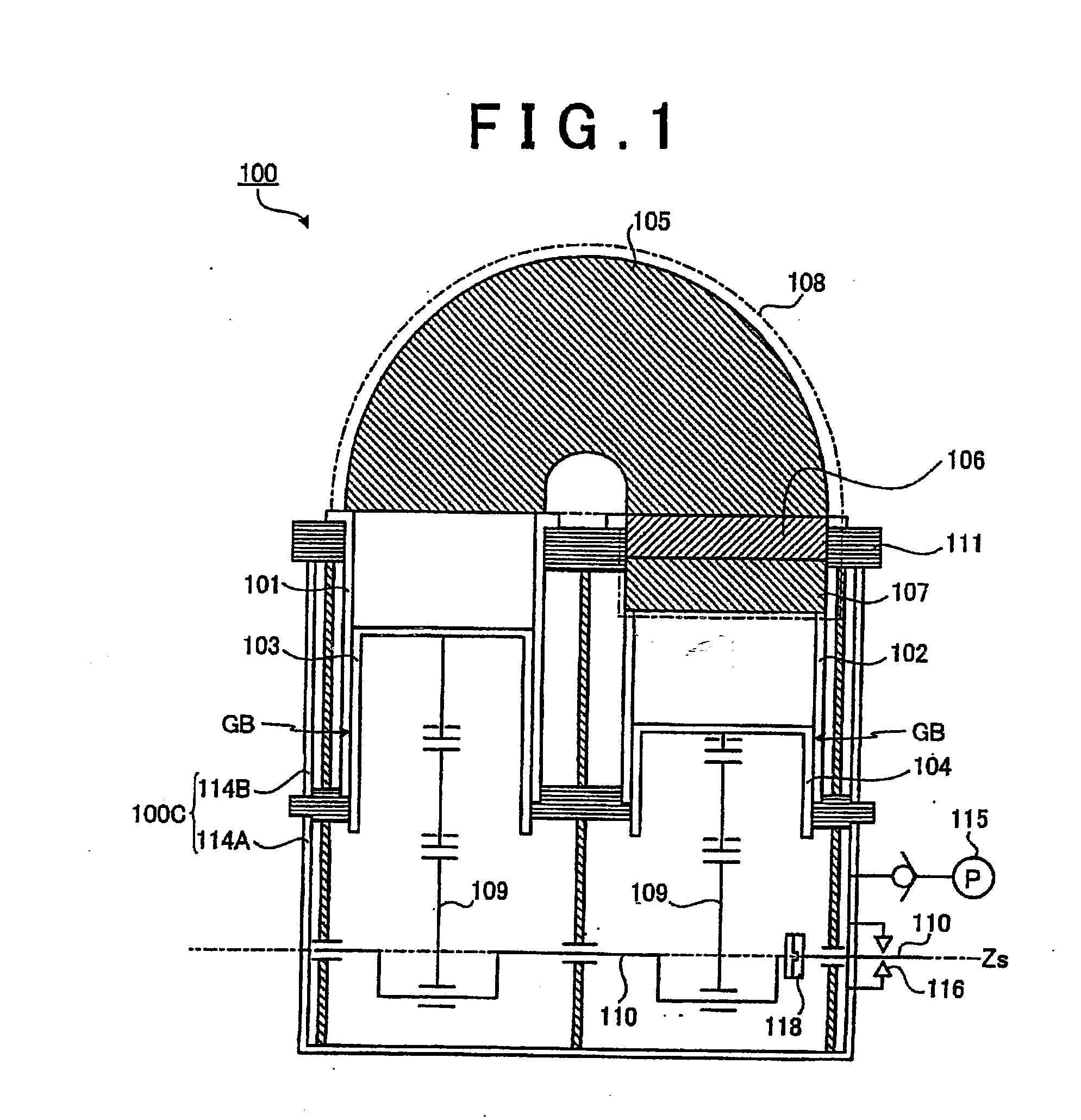
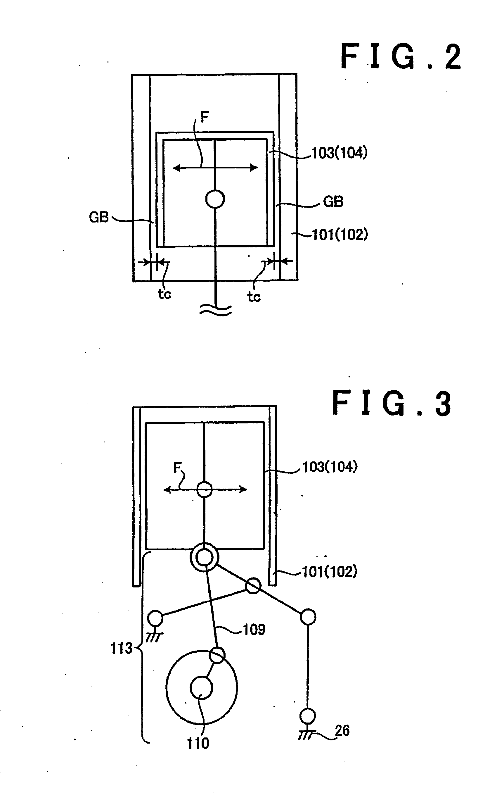
[0032]The high temperature-side cylinder 10 and the low temperature-side cylinder 102 are directly or indirectly supported by, or fixed to a base plate 111, which is a reference body. The base plate 111 serves as a positional reference of the components of the Stirling engine 100. With this configuration, it is made possible to ensure the accuracy of the relative position between the components. In addition, as described later, in the Stirling engine 100 of the first embodiment, respective gas bearings GB are interposed between the high temperature-side cylinder 101 and the high temperature-side piston 103, and between the low temperature-side cylinder 102 and the low temperature-side piston 104. By fixing the high temperature-side cylinder 101 and the low temperature-side cylinder 102 directly or indirectly to the base plate 111, which is the reference body, it is possible to maintain the clearance between the piston and the cylinder with precision. Thus, the function of the gas be...

second embodiment

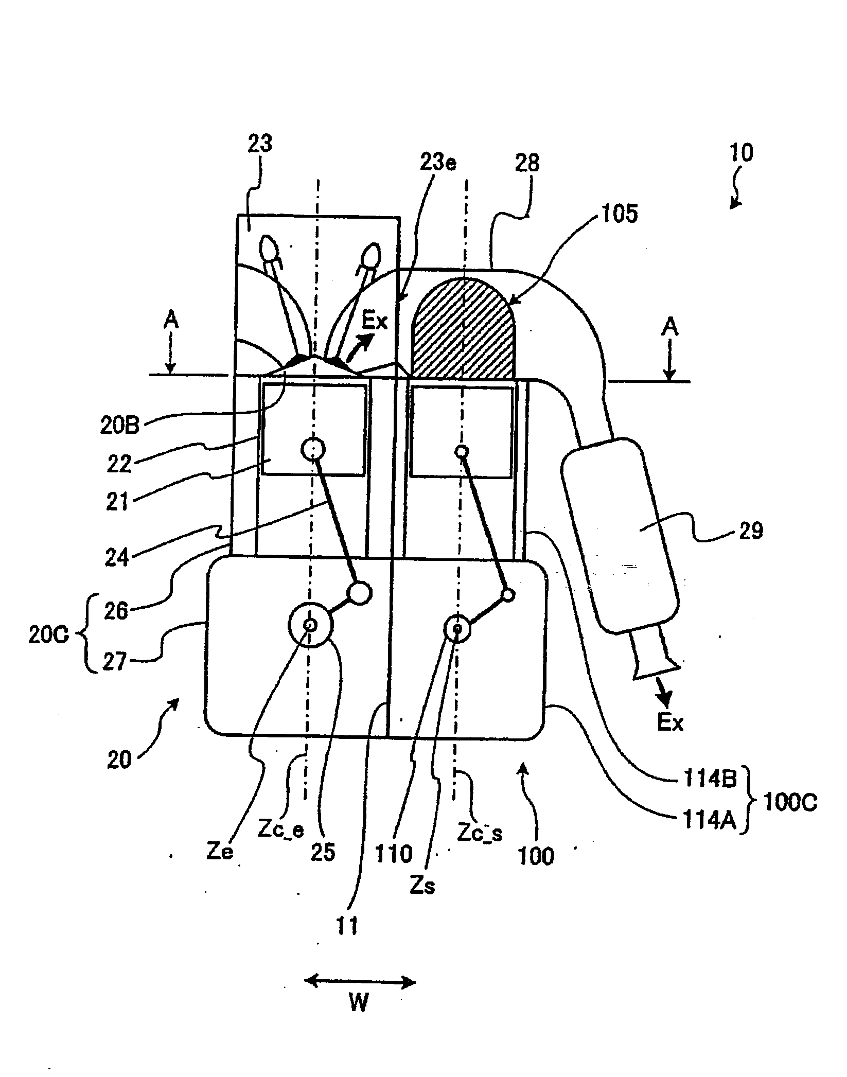
[0058]FIG. 7 is an explanatory diagram showing an exhaust heat recovery apparatus according to the present invention. The exhaust heat recovery apparatus 10′ is substantially the same as the exhaust heat recovery apparatus 10 (see FIG. 4), except that the central axis Zc_e of a cylinder of the internal combustion engine 20 and the central axis Zc_s of the adjacent cylinder of a Stirling engine 100′ are inclined with respect to each other.

[0059]In the exhaust heat recovery apparatus 10′, the central axis Zc_e of a cylinder of the internal combustion engine 20 and the central axis Zc_s of the adjacent cylinder of the Stirling engine 100′ are inclined with respect to each other by a predetermined angle ?. Thus, an exhaust heat recovery means-side cylinder block 114B′ constituting an exhaust heat recovery means-side housing 100C′ of the Stirling engine 100′, and the heat engine-side cylinder block 26 constituting the heat engine-side housing 20C of the internal combustion engine 20 are ...

third embodiment

[0061]FIGS. 8 and 9 are explanatory diagrams showing an exhaust heat recovery apparatus according to the present invention. FIGS. 8 and 9 are a front view and a plan view, respectively. The exhaust heat recovery apparatus 10a is formed by combining two exhaust heat recovery apparatuses 10 (see FIGS. 4 to 6) in a V shape when viewed along the direction of the internal combustion engine-side rotation axis Ze. That is, the cylinders of the internal combustion engine 20 are arranged in a V shape.

[0062]In this case, the exhaust ports 23e and the exhaust manifolds 28 of the internal combustion engine 20 are provided on the outer sides of the exhaust heat recovery apparatus 10a in the width direction thereof, so that the Stirling engines 100 are also provided on the outer sides of the exhaust heat recovery apparatus 10a in the width direction thereof. In the exhaust heat recovery apparatus 10a shown in FIG. 8, the exhaust heat recovery means-side crankshaft 110 and the heat engine-side cra...


PUM


Abstract

An exhaust heat recovery apparatus includes a reciprocating internal combustion engine in which a piston reciprocates in a cylinder to generate motive power; and a Stirling engine that recovers the thermal energy of the exhaust gas discharged from the internal combustion engine and converts the thermal energy into kinetic energy. The Stirling engine is united with the internal combustion engine. A heater that the Stirling engine includes is disposed in an exhaust manifold of the internal combustion engine. With this configuration, it is possible to restrict reduction in the power output from the exhaust heat recovery means.

Description

BACKGROUND OF THE INVENTION[0001]1. Field of the Invention[0002]The present invention relates to an exhaust heat recovery apparatus for recovering the exhaust heat from a heat engine.[0003]2. Description of the Related Art[0004]An exhaust heat recovery apparatus is available that, using a heat engine, recovers the exhaust heat from an internal combustion engine that is mounted on a vehicle, such as a passenger car, a bus and a truck. As an example of the exhaust heat recovery apparatus used for such a purpose, there is the Stirling engine, which is excellent in theoretical thermal efficiency. Japanese Patent Application Publication No. 2005-113810 (JP-A-2005-113810) discloses a Stirling engine used as an exhaust heat recovery device that recovers the thermal energy of the exhaust gas from an internal combustion engine.[0005]The Stirling engine is prepared separately from the internal combustion engine, and is provided on an exhaust gas passage of the internal combustion engine. The ...

Claims


Application Information

Patent Timeline
Patent Type & Authority Applications(United States)
IPC IPC(8): F02G1/043F02G5/02
CPCF02G1/043Y02T10/166F02G2254/15F02G5/02Y02E20/30Y02T10/12
Inventor YAGUCHI, HIROSHISAWADA, DAISAKUMITANI, SHINICHI
Owner TOYOTA JIDOSHA KK
Why Eureka
Try Eureka