Portable gas generating device and electrical fuel cell power supply comprising such a device

a gas generating device and power supply technology, applied in the direction of fuel cells, acetylene gas generators, inorganic chemistry, etc., can solve the problems of low overall energy production efficiency, small devices, and high flammability of hydrogen,

Active Publication Date: 2009-01-15
COMMISSARIAT A LENERGIE ATOMIQUE ET AUX ENERGIES ALTERNATIVES
View PDF13 Cites 20 Cited by
  • Summary
  • Abstract
  • Description
  • Claims
  • Application Information

AI Technical Summary

Problems solved by technology

Moreover, they must be especially secure because hydrogen is very flammable.
Consequently, this type of storage cannot be used in portable, and especially small, devices.
However, the overall energy production efficiency is relatively low.
However, this method of preparing hydrogen implements a heterogeneous reaction between liquid and solid, and consequently the kinetics of this reaction are inferior to those of a reaction between two compounds in the same state.
Moreover, in the case o

Method used


Image

  • Portable gas generating device and electrical fuel cell power supply comprising such a device
  • Portable gas generating device and electrical fuel cell power supply comprising such a device
  • Portable gas generating device and electrical fuel cell power supply comprising such a device

Examples


first embodiment

[0017]In a first embodiment, the hydrogen generating device is controlled manually, for example by means of a thumb wheel arranged outside a housing of the hydrogen generating device containing the tank and the reaction chamber. In an alternative embodiment, the injection is controlled by an electric motor.

[0018]In an advantageous embodiment, the hydrogen generation is controlled automatically by the hydrogen gas produced in the reaction chamber. The chemical reactor thus provided is capable of operating in all positions with reduced bulk, and the activation and stopping of the hydrogen production are controlled manually or automatically.

[0019]The solid reactant can, for example, by a metal borohydride or a mixture of a plurality of reactants to which a catalyst or a reaction activator can be added. The aqueous solution can also advantageously contain a reaction activator solubilized in the aqueous solution.

third embodiment

[0020]In a third embodiment, the reaction chamber contains a solid catalyst and the tank can contain aqueous solution with hydride.

[0021]The invention therefore involves moving the leading edge of the reaction between the solid compound and the liquid compound so as to prevent the reaction from being stopped by clogging of the reactants.

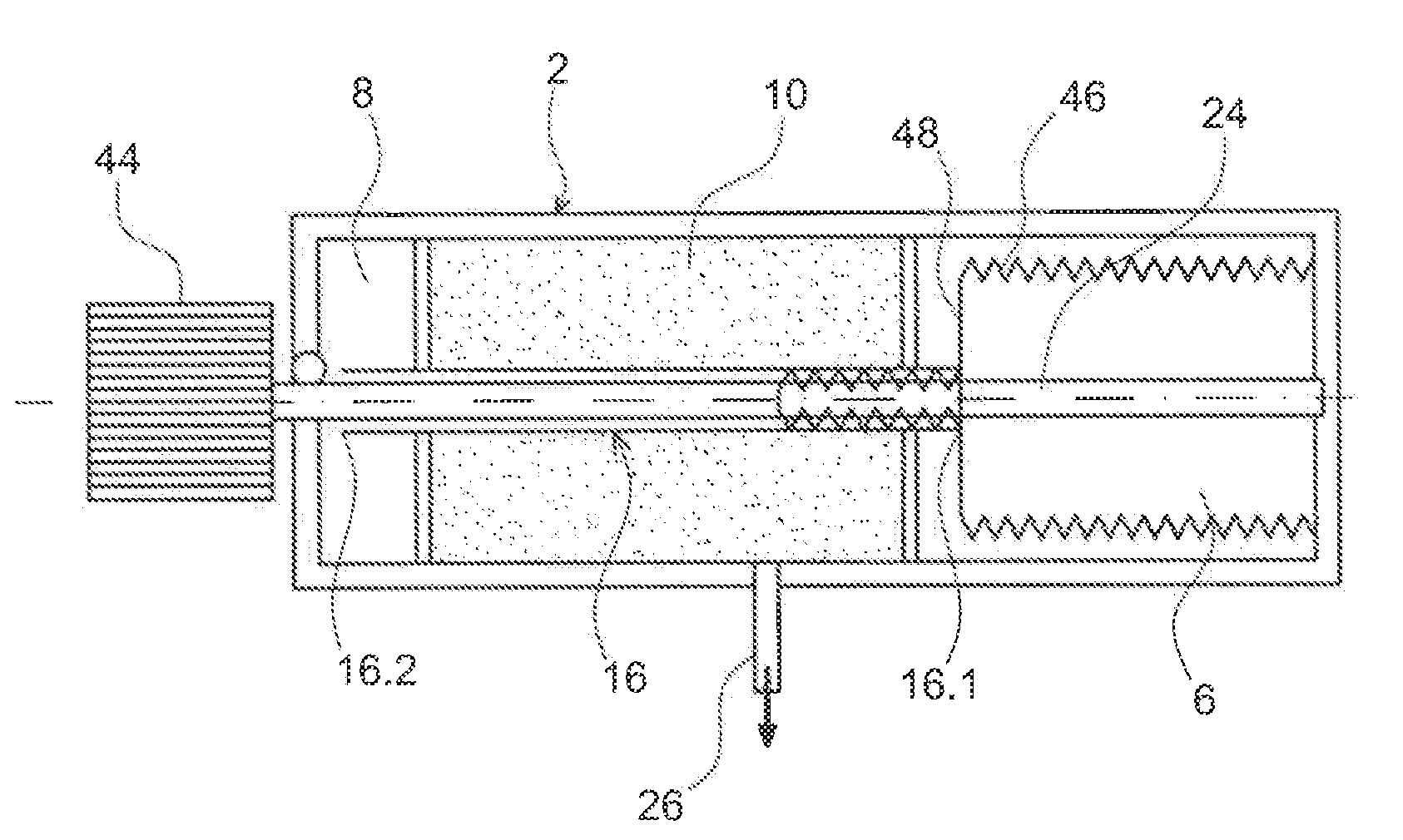
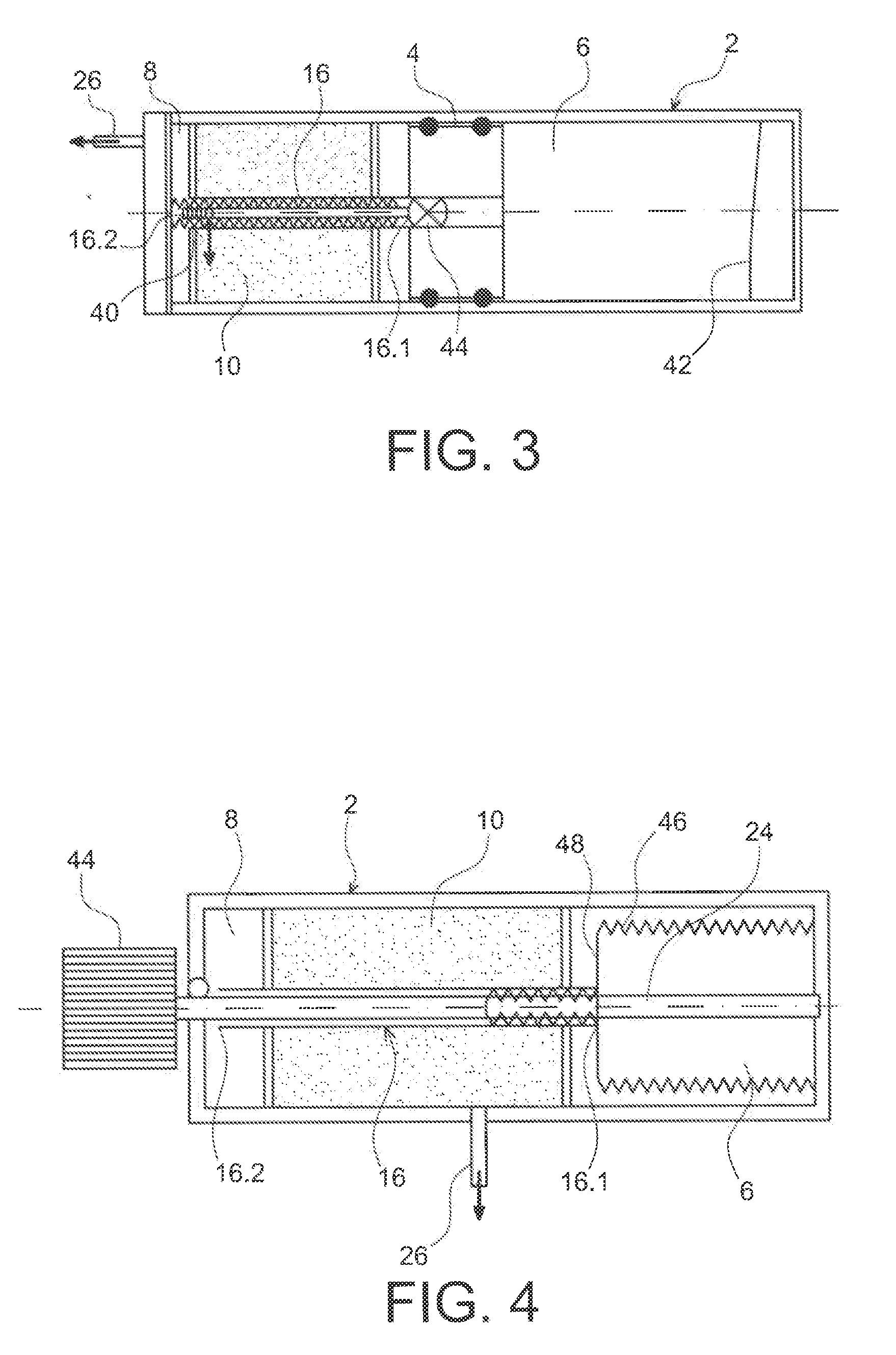
[0022]For example, the liquid, in particular the aqueous solution, is injected onto the solid component by means of a tube of which the end moves with respect to the solid component as the liquid reactant is introduced into the reaction chamber. Consequently, the liquid always reacts with a new area of the solid component.

[0023]The device also has the advantage of implementing stable products separated before the reaction, although a solution, even when stabilized, breaks down over the long term. Consequently, the generator can be preserved for a longer time and work when needed.

[0024]It is possible to use pasty or solid reaction products, without th...

second embodiment

[0051]FIG. 4 is a diagrammatic longitudinal cross-section view of a hydrogen generating device according to the present invention with automatic activation,

[0052]FIG. 5 is a diagrammatic drawing of a portable apparatus according to the present invention electrically powered by a fuel cell supplied with hydrogen by a hydrogen generating device according to the invention,

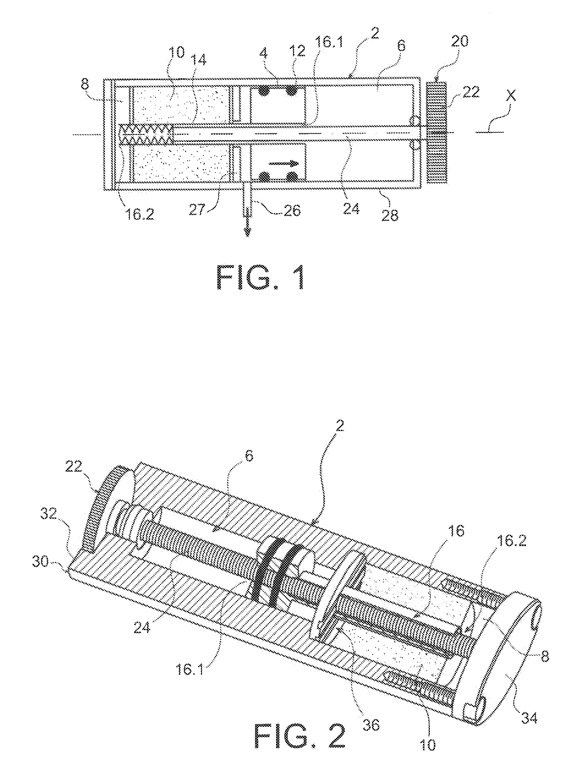
[0053]FIG. 6A is a longitudinal cross-section view of an industrial embodiment of the device of FIG. 4,

[0054]FIG. 6B is an enlarged perspective view of FIG. 6A.


PUM

PropertyMeasurementUnit
Pressureaaaaaaaaaa
Volumeaaaaaaaaaa
Flexibilityaaaaaaaaaa

Abstract

Device for generating gas by placing a liquid reactant in contact with a solid element, comprising a liquid reactant tank (6) and a reaction chamber (8) intended to contain the solid element, wherein the tank (6) and the reaction chamber (8) are separated in a sealed manner by a mobile wall (4), with an outlet port (26) for collecting the gas generated in the reaction chamber and means (14) for injecting the liquid reactant onto the solid element, which injection means (14) pass through the mobile wall (4) and are capable of moving into the solid element.

Description

PRIOR ART[0001]This invention relates to a portable gas generating device, and more specifically to a portable hydrogen generator, in particular for a fuel cell comprising such a gas generator, in particularly a hydrogen generator and electrically powered portable elements comprising such a fuel cell.[0002]The search for a clean energy source is becoming increasingly important, in particular due to diminishing oil resources as well as the impact of fossil fuel use on the environment. Fuel cells, in particular hydrogen fuel cells, make it possible to produce electricity with minimal impact on the environment. These fuel cells use hydrogen as a raw material to produce electricity by electrochemical reaction.[0003]Hydrogen can be supplied either by a hydrogen tank in the form of pressurized gas, or in liquid form, but this storage requires high-capacity tanks. Moreover, they must be especially secure because hydrogen is very flammable. Consequently, this type of storage cannot be used ...

Claims


Application Information

Patent Timeline
IPC IPC(8): H01M8/06B01J8/00B01J7/00C01B3/02
CPCB01J7/02C01B3/065C01B7/01C01B7/04C01B13/0211C10H1/08Y02E60/50H01M8/04216H01M8/0606H01M8/0612H01M8/0631H01M8/065Y02E60/362C10H21/00Y02E60/36
Inventor DAMERY, EMMANUELDELMAS, JEROMELAURENT, JEAN-YVESVALON, BRUNO
Owner COMMISSARIAT A LENERGIE ATOMIQUE ET AUX ENERGIES ALTERNATIVES
Why Eureka
Try Eureka