Vertebra attachment method and system

a technology of vertebrae and attachment methods, applied in the field of new vertebrae attachment methods and systems, can solve the problems of subacute or acute compression of the upper spinal cord, significant neurological problems, and compression of the medulla oblongata, and achieve the effects of minimizing or eliminating reducing the necessary duration of surgical procedures, and reducing the risk of severing

Active Publication Date: 2009-01-15
LIFE SPINE INC
View PDF99 Cites 37 Cited by
  • Summary
  • Abstract
  • Description
  • Claims
  • Application Information

AI Technical Summary

Benefits of technology

[0025]Accordingly, it is an object of the invention to provide a method and system that accomplishes the goals of: successfully minimizing or eliminating the risk of severing, compressing, impinging or otherwise injuring the vertebral artery, vertebral vein, spinal nerve roots and/or spinal cord; developing a vertebral attachment s

Problems solved by technology

Spinal instability is a severe problem, and may cause chronic, subacute or acute compression of the upper spinal cord.
Instability of the uppermost vertebrae, C1 and C2, may result in compression of the medulla oblongata, and may cause significant neurological problems, such as altered sensation and motor function, altered respiratory function, altered cardiac, gastrointestinal, bowel and bladder function, or altered function of the autonomic nervous system.
Compression may also cause neck pain, headache and bulbar symptoms, such as altered vision and hearing, difficulties with swallowing, altered speech, sleep apnea, numbness and weakness of the arms and legs, urinary urgency or incontinence, or the progressive loss of ability to walk.
Although proven to have superior biomechanical capabilities and fusion rates in comparison to wiring techniques, screw fixation is a demanding technique and carries a substantial risk of injuring vertebral artery A12.
The method can be highly dangerous, potentially severing or causing substantial harm to the vertebral artery A12, shown in FIG. 6.
Blockage or thrombosis of the vertebral artery A12 can result in immediate brainstem stroke, “locked-in syndrome,” or death.
The vertebral artery A12 may also be injured during the surgical exposure of the operative site.
In each case, the vertebral artery A12 in its anomalous course is at an increased risk of injury.
Moreover, dissection of the lateral aspect of the lateral mass of C1 may result in injury and tearing of the vertebral artery A12 because: artery A12 frequently sits in an exposed position

Method used


Image

  • Vertebra attachment method and system
  • Vertebra attachment method and system
  • Vertebra attachment method and system

Examples


Embodiment Construction

[0059]For illustrative purposes, the principles of the present invention are described by referencing various exemplary embodiments. Although certain embodiments of the invention are specifically described herein, one of ordinary skill in the art will readily recognize that the same principles are equally applicable to, and can be employed in other systems and methods. Before explaining the disclosed embodiments of the present invention in detail, it is to be understood that the invention is not limited in its application to the details of any particular embodiment shown. Additionally, the terminology used herein is for the purpose of description and not of limitation. Furthermore, although certain methods are described with reference to steps that are presented herein in a certain order, in many instances, these steps may be performed in any order as may be appreciated by one skilled in the art; the novel method is therefore not limited to the particular arrangement of steps disclo...


PUM


Abstract

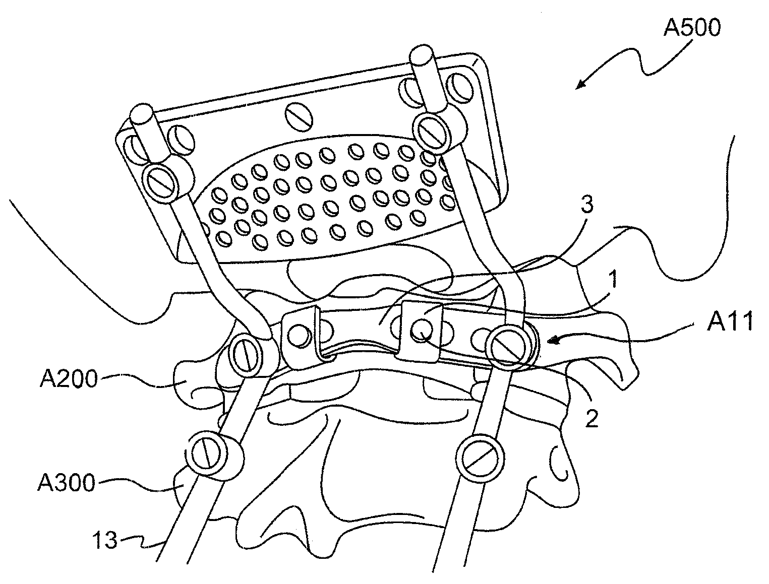
A vertebral attachment method and system that minimizes or eliminates the risk of severing, compressing, impinging or otherwise injuring the vertebral artery vertebral vein, spinal nerve roots and/or spinal cord. The system includes at least one plate that may be anchored to a posterior region of a vertebra using at least one clamp and fastener. The system may be specifically designed to retain a portion of the posterior region of the vertebra.

Description

CROSS-REFERENCE TO RELATED APPLICATIONS[0001]This application is a continuation in part of U.S. patent application Ser. No. 11 / 832,643, filed on Aug. 1, 2007, which in turn claims the benefit of U.S. Provisional Patent Application No. 60 / 887,022, filed on Jan. 29, 2007; continuation in part of U.S. patent application Ser. No. 11 / 832,646, filed on Aug. 1, 2007, which in turn claims the benefit of U.S. Provisional Patent Application No. 60 / 887,022, filed on Jan. 29, 2007; and further benefit of U.S. Provisional Patent Application No. 60 / 987,567, filed Nov. 13, 2007; the entire disclosures of which are incorporated herein by reference.BACKGROUND OF THE INVENTION[0002]1. Field of Invention[0003]The present invention is directed to a novel vertebra attachment method and system. Specifically, the invention pertains to a vertebra attachment method and system that may be used in spinal stabilization applications, such as fusing the occipitocervical junction and / or the spinal vertebrae.[0004...

Claims


Application Information

Patent Timeline
IPC IPC(8): A61B17/70A61B17/04A61B19/00
CPCA61B17/7011A61B17/7047A61B17/7049A61B17/7052A61B17/7055A61B17/7082A61B17/7062A61B17/8085A61B17/8605A61B17/863A61B2017/00004A61B17/7056
Inventor HENDERSON, SR., FRASER CUMMINSNEWMAN, JOHN W.
Owner LIFE SPINE INC
Why Eureka
Try Eureka