

Catalytic element
a catalytic element and element technology, applied in the field of catalytic elements, can solve the problems of not supporting the reforming reaction of hydrocarbons or tar compounds in feed gases like syngas or crude natural gas, ceramic bodies may not be used successfully for other types of catalytic gas phase reactions, etc., to achieve the effect of reducing flow resistance, reducing pore volume, and improving mechanical stability
- Summary
- Abstract
- Description
- Claims
- Application Information
AI Technical Summary
Benefits of technology
Problems solved by technology
Method used
Image

Examples
example 1
Manufacture of a Catalytic Element
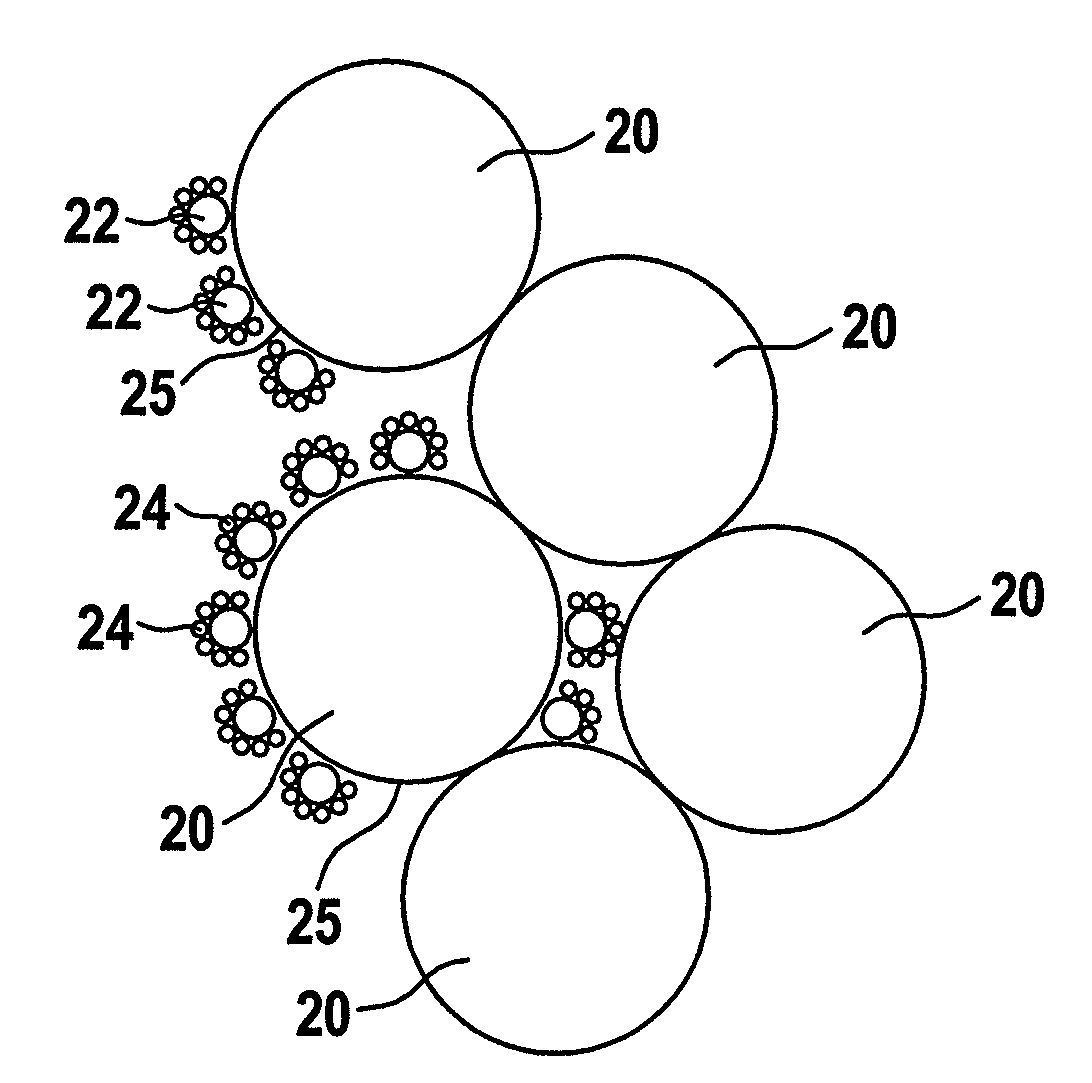
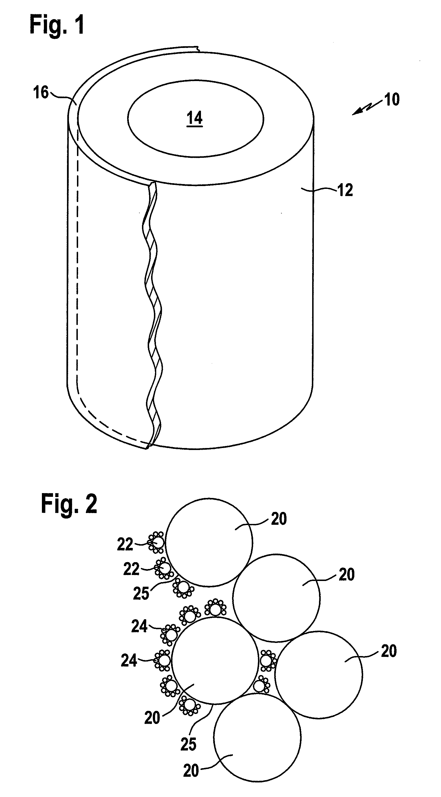
[0097]The porous ceramic bodies, used for manufacturing of inventive catalytic element 10 were of a hollow cylindrical shape and had an outer diameter of 60 mm, an inner diameter of 40 mm and a length of 50 mm.
[0098]The porous ceramic bodies consisted of sintered SiC grains of two different primary particle sizes. The average sizes of the SiC grains were about 250 μm and about 150 μm, respectively. The average pore size of the ceramic body was approximately 50 μm.
[0099]The outer surface of the cylindrical structure used as upstream surface was provided with a membrane filter layer 16. The filter layer 16 had a thickness of approximately 200 μm on average and consisted of sintered mullite particles of an average particle size of about 40 μm. The pore size of the filter layer 16 was approximately 10 μm.
[0100]Such porous bodies 12 with membrane filter layers 16 are commercially available as DIA-SCHUMALITH 10-20 from Pall Filtersystems GmbH Werk Schumac...
example 2
Use of an Inventive Catalytic Element for Tar Removal
[0119]A catalytic filter element 10 prepared according to Example 1 was used in this Example
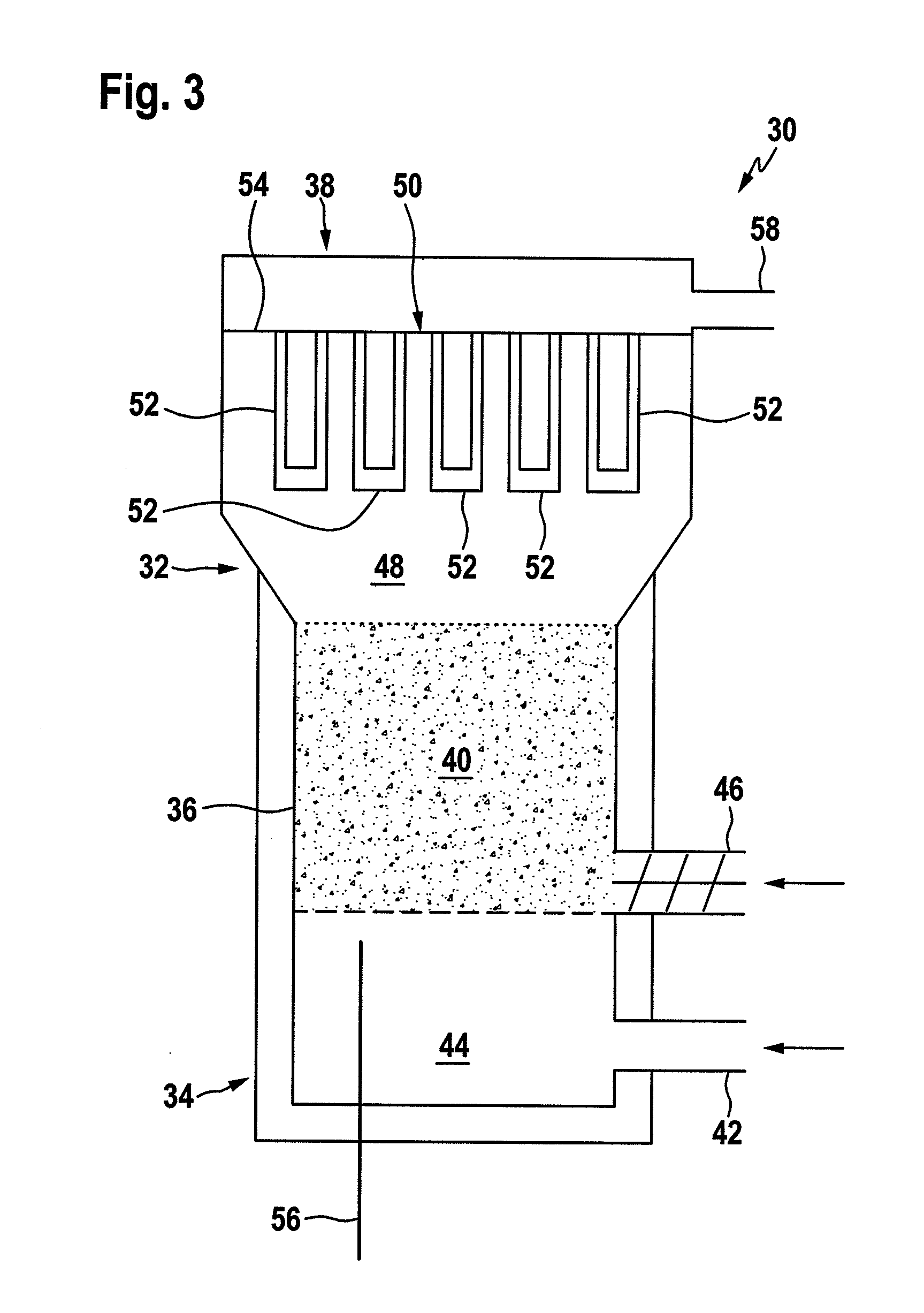
[0120]The tar removal performance of the catalytic filter element 10 was examined in the temperature range of from 700 to 900° C. using a circular segment cut out from the catalytic filter element 10 and fixed in an alumina tube reactor. A model biomass gasification gas consisting of 50 vol % N2, 12 vol % CO, 10 vol % H2, 11 vol % CO2, 5 vol % CH4 and 12 vol % H20 was used comprising 5 g / Nm3 naphthalene as tar model compound.
[0121]A constant face velocity of 90 m / h was adjusted at all temperature settings, and the naphthalene conversion was measured in the absence and presence of H2S. The absolute preparation and measurement error was at ±10%. The results are reported in Table I.
TABLE INaphthalene conversion inNaphthalene convention in theTemperaturethe absence of H2Spresence of 100 ppmV H2S[° C.][%][%]70083.46.7750n.m.16.880097.844.9850n.m...
example 3
Use of Another Inventive Catalytic Element for Tar Removal
[0123]In this Example a catalytic filter element 10 with a NiO loading of about 60 wt % was used. For depositing the catalyst material on the basic oxide material coated pore surface of a catalytic filter element as prepared in Example 1 a solution of 28 g nickel nitrate hexahydrate in 180 g deionized water was used while all other preparation parameters as described above were observed.
[0124]The obtained catalytic filter element 10 was tested under the same conditions as reported in Example 2. An improved naphthalene conversion of 57.8% in the presence of 100 ppmV H2S at 800° C. in comparison to 44.9% of the catalytic filter element with a NiO loading of 120 wt % (cf. Tab. I and II for comparison) was observed.
TABLE IINaphthalene conversion inNaphthalene convention in theTemperaturethe absence of H2Spresence of 100 ppmV H2S[° C.][%][%]70091.64.7750n.m.2280096.857.8850n.m.78.790099.889.8n.m. = not measured.
PUM
| Property | Measurement | Unit |
|---|---|---|
| Temperature | aaaaa | aaaaa |
| Temperature | aaaaa | aaaaa |
| Pore size | aaaaa | aaaaa |
Abstract
Description
Claims
Application Information