Method for manufacturing heat radiator having plate-shaped fins
a technology of heat radiator and fin, which is applied in the field of heat radiator, can solve the problems of difficult scrapping of fin, inability to gouge out the radiating fin, and inability to remove thin, and achieve the effect of high efficiency and heat radiation
- Summary
- Abstract
- Description
- Claims
- Application Information
AI Technical Summary
Benefits of technology
Problems solved by technology
Method used
Image
Examples
embodiment 1
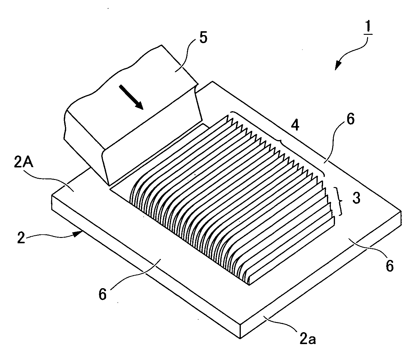
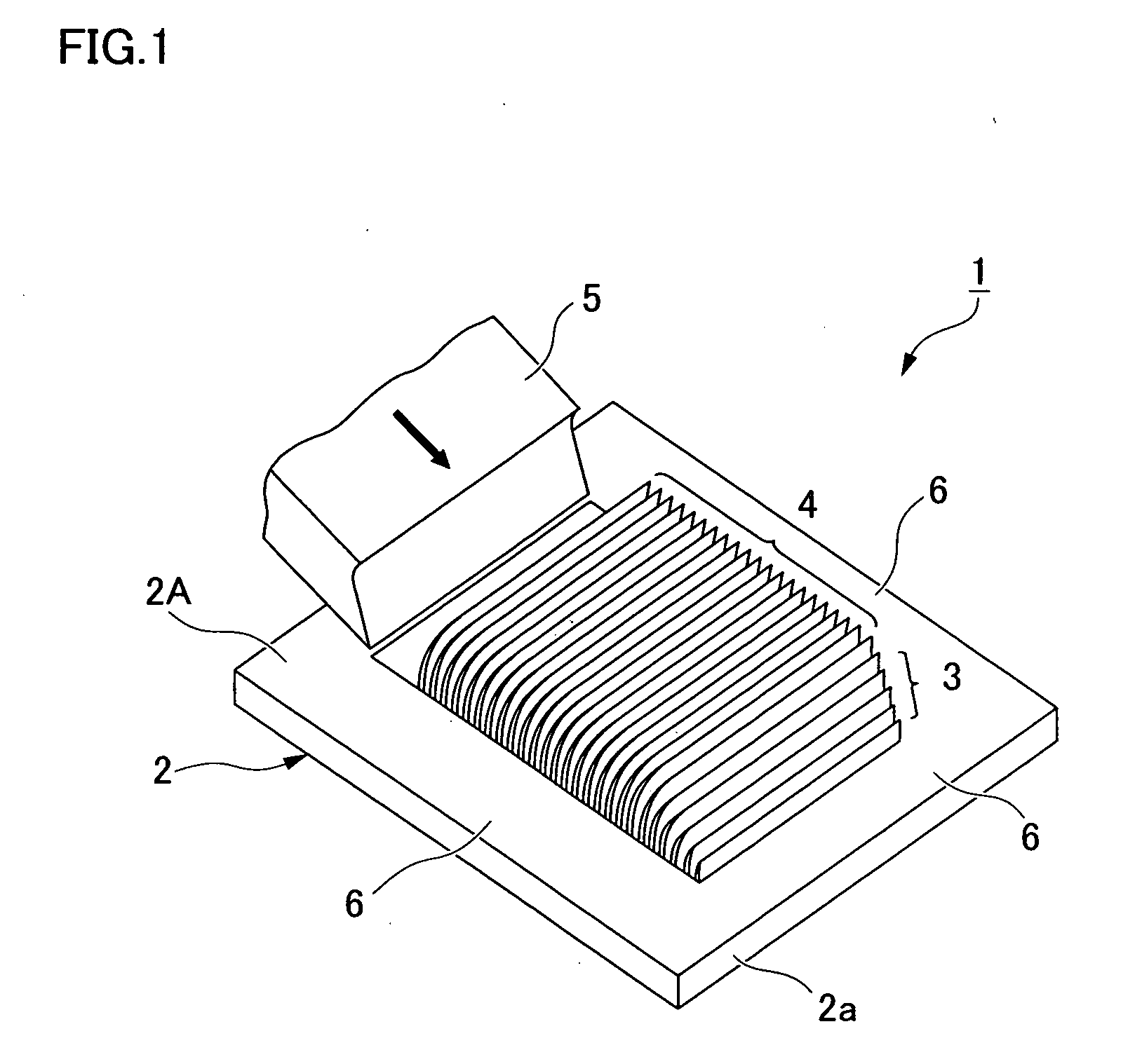
[0047]FIG. 1 is a perspective view showing a heat radiator having plate-shaped heat-radiating fins according to Embodiment 1. A plastically workable metal material having a high coefficient of thermal conductivity can be used for the metal plate 2 used in a heat radiator 1. For example, it is possible to use a rectangular metal plate 2 having a uniform thickness and formed from aluminum, aluminum alloy, copper alloy, stainless steel, or another metal material.
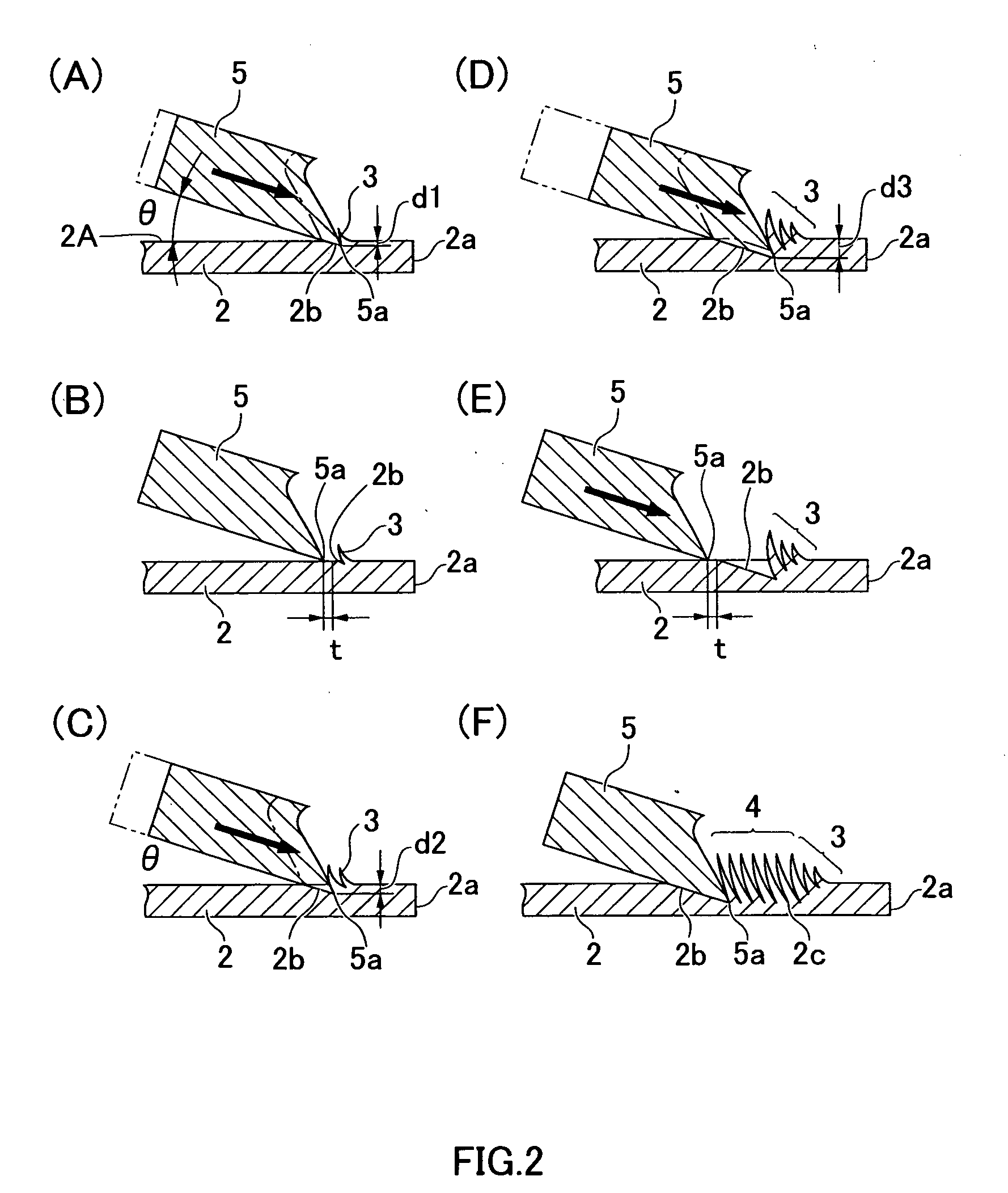
[0048]A plurality of small, low fins 3 is formed in a section (at a prescribed position set at a distance from one end of the metal plate) located inward from an outside edge 2a of a surface 2A (one of the surfaces) of the metal plate 2. Subsequent to these small fins 3, thin plate-shaped heat-radiating fins 4 having the same height are formed. The small fins 3 are formed from one outside edge 2a of the metal plate 2 so as to gradually increase in height until the heat-radiating fins 4 are reached. The base-end portion of the s...
embodiment 2
[0067]FIG. 5 shows an example in which a hoop-shaped metal plate 10 is used as the metal plate in the method for manufacturing a heat radiator having plate-shaped fins according to the present invention. The hoop-shaped metal plate 10 can be plastically worked in the same manner as in Embodiment 1 described above, and aluminum, aluminum alloy, copper alloy, stainless steel, or another metal material is used as the metal material having a high coefficient of thermal conductivity.
[0068]A plurality of heat-radiating fins 4 is formed subsequent to the formation of the plurality of small fins 3 in the same manner as in Embodiment 1 described above on the hoop-shaped metal plate 10 as well, to form a first fin group 11. A plurality of heat-radiating fins 4 is formed subsequent to the formation of the plurality of small fins 3 to form a second fin group 12 separated by spaces 13 at prescribed intervals, and fin groups are sequentially formed while providing the spaces 13 at prescribed inte...
embodiment 3
[0070]FIG. 6 shows an embodiment in which a pair of fin groups on the left and right are formed by forming a plurality of small fins from the center of the metal plate, followed by a plurality of heat-radiating fins in the method for manufacturing the heat radiator having plate-shaped fins according to the present invention.
[0071]In the embodiment shown in FIG. 6, the blade section of the gouging tool 5 is brought into contact with a prescribed position at the center of the metal plate 20 in the same manner as in the formation method shown in FIG. 2 described above, the blade section 5a of the gouging tool 5 is thereafter made to bite into a surface of the metal plate 20 at a prescribed angle, and a thin small fin 3 having a low profile is formed upright. Afterward, the small fin is formed upright a plurality of times until the blade section 5a of the gouging tool 5 reaches a prescribed depth. A transition is thereafter made to the fin formation step subsequent to the upright format...
PUM
| Property | Measurement | Unit |
|---|---|---|
| width | aaaaa | aaaaa |
| slope angle | aaaaa | aaaaa |
| gouging width | aaaaa | aaaaa |
Abstract
Description
Claims
Application Information
 - R&D
- Intellectual Property
- Life Sciences
- Materials
- Tech Scout
- Unparalleled Data Quality
- Higher Quality Content
- 60% Fewer Hallucinations
Browse by: Latest US Patents, China's latest patents, Technical Efficacy Thesaurus, Application Domain, Technology Topic, Popular Technical Reports.
© 2025 PatSnap. All rights reserved.Legal|Privacy policy|Modern Slavery Act Transparency Statement|Sitemap|About US| Contact US: help@patsnap.com


