Omni-directional antenna for mobile satellite broadcasting applications

Inactive Publication Date: 2009-01-29
JAST
View PDF3 Cites 24 Cited by
  • Summary
  • Abstract
  • Description
  • Claims
  • Application Information

AI Technical Summary

Benefits of technology

[0034]According to another embodiment of the invention, the space between the ground plane and the at least first and second radiating elements is filled with an at least first dielectric layer. The dielectric layer typically comprises a relative permittivity εr larger than 1. In this way, the overall size

Problems solved by technology

Moreover, in modern broadcasting systems, the satellite coverage is some times supported by terrestrial repeaters, in particular in those urban areas, where buildings may prevent a line-of-sight to a satellite and in which the satellite signal is not sufficiently available.
Hence, PIFA antenna designs have drawbacks with respect to requirements of mobile satellite systems.
In particular, the fairly broad coverage limits the maximum value of the antenna directivity.
Another drawback is that the variation of the level of the directivity in Azimuth causes a degree of the reception quality depending on the orientation of the vehicle, on which the antenna is mounted.
Other antenna types, such a patch antennas, PIFA compact antennas, ¾ and ¼ of wave length antennas, monopole antennas, dipole antennas, and disc antennas also have common drawbacks, in particular when a very small size of the antenna is required.
Nevertheless, the performances are generally affected in far field by the lower directivity due to the reduced effective aperture area of the small antenna.
Moreover, even if the small antenna design has a radiation pattern and a directivity being rather independent on the frequency, their impedance matching is very difficult, because the resistanc

Method used


Image

  • Omni-directional antenna for mobile satellite broadcasting applications
  • Omni-directional antenna for mobile satellite broadcasting applications
  • Omni-directional antenna for mobile satellite broadcasting applications

Examples


Example

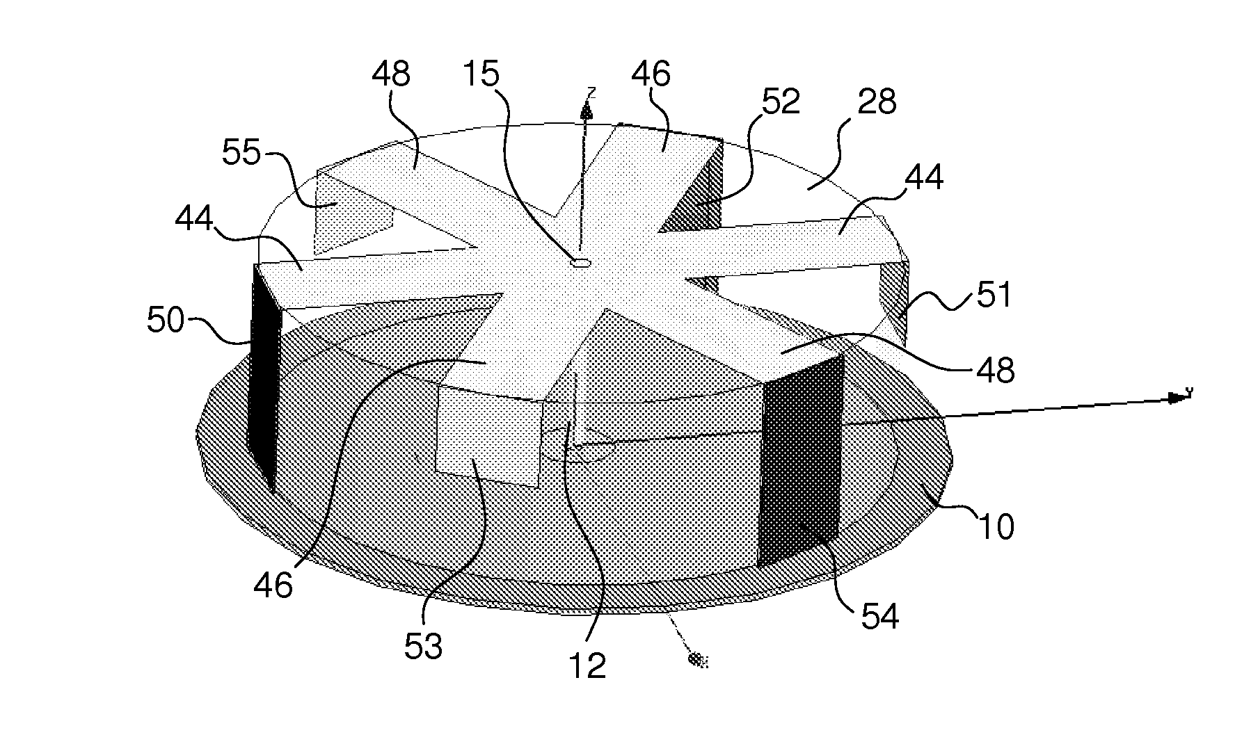
[0064]The present invention aims to provide an antenna for mobile satellite communication providing a maximum coverage at an elevation ranging between 20° to 60°, while still ensuring a good level of directivity at a range of 5° to 15° of elevation in order to receive signal broadcasting by terrestrial repeaters. Further, the antenna according to the present invention may be able to receive simultaneously a vertically polarized signal at 5° to 15° of elevation and a dual circularly polarized signal at 20° to 60° of elevation.

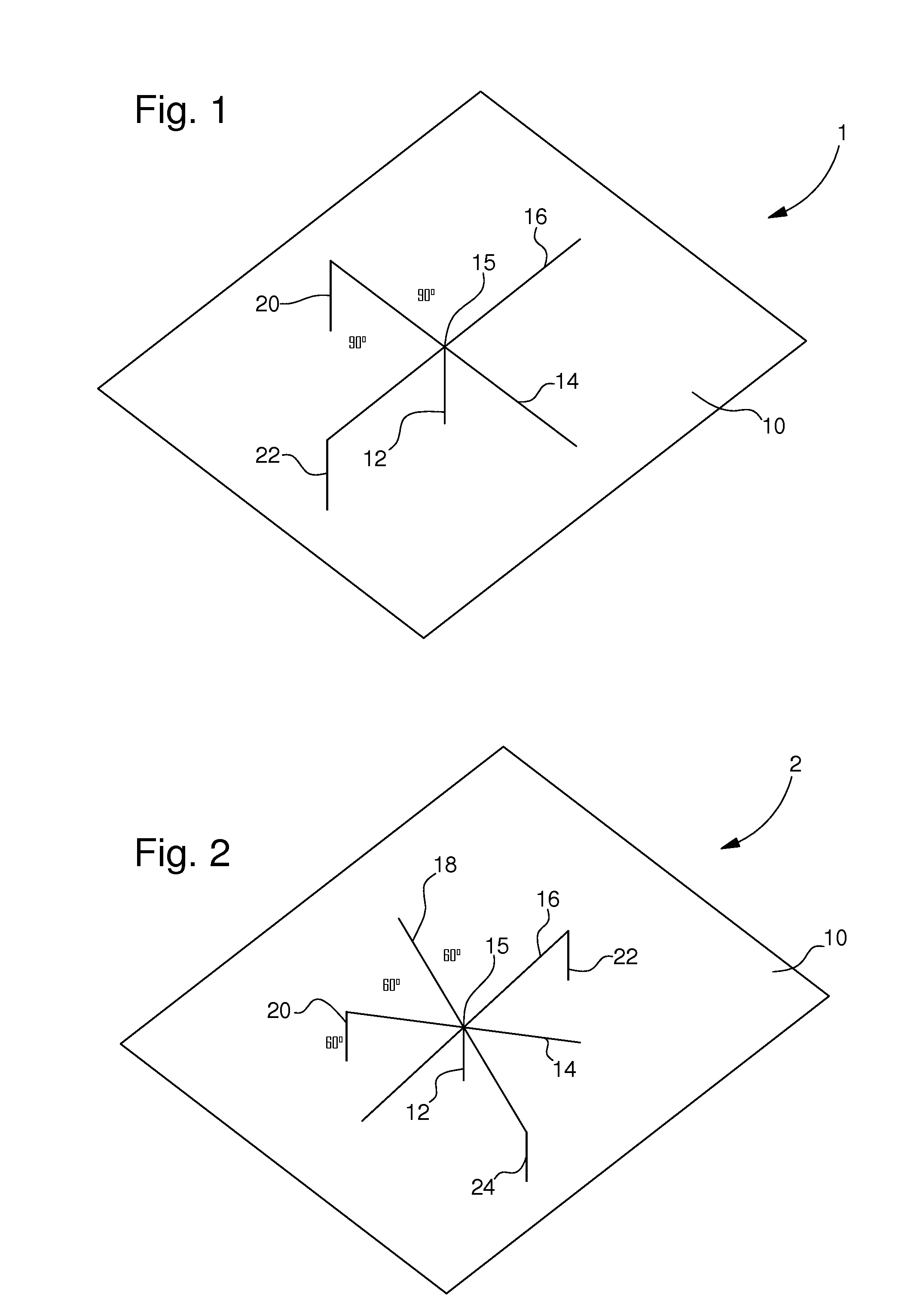
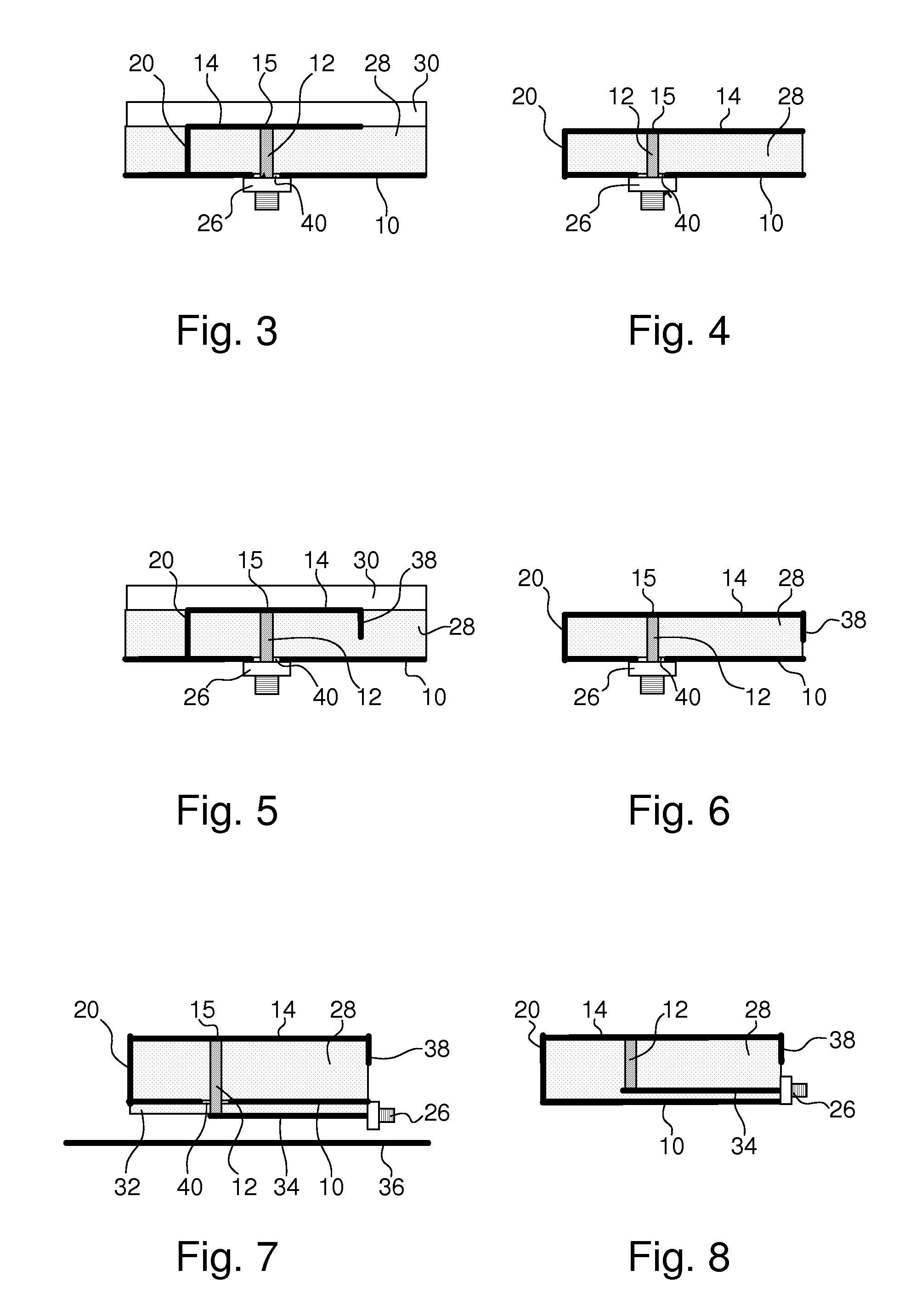
[0065]The antenna 1 according to FIG. 1 comprises a ground plane 10 and a first radiating element 14 as well as a second radiating element 16. The two radiating elements 14, 16 are designed as transmission lines. They both intersect at a feeding point 15 that coincides with an end section of the feed line 12 extending substantially parallel to the surface normal of the ground plane 10.

[0066]In this embodiment, the two transmission lines 14, 16 extend at an angle...


PUM


Abstract

An antenna for mobile satellite communication is disclosed. The antenna may include an electrically conducting ground plane and at least a first and a second radiating element. Each one of the radiating elements may be electrically coupled to a feed line, whereby each one of said at least first and second radiating elements may be electrically connected to the ground plane at one end and being open-circuit at an opposite end, whereby the at least first and second radiating elements may intersect at a feeding point of the feed line and extend radially with respect to the elongation of the feed line.

Description

BACKGROUND OF THE INVENTION[0001]The invention generally relates to an antenna for vehicular mobile applications using mobile satellite systems, and more particularly, to a multiple planar inverted F-antenna with a conical radiation pattern with high directivity in the range of low elevation angle above the horizon. The invention is pre-dominantly related to be designed for but not limited to a car-roof antenna for satellite communications.[0002]In recent years, many new satellite based services for vehicular applications have come into service. These services include applications such as satellite communications or global positioning systems. Compact antennas, generally arranged on the top of a vehicle are required to receive these kinds of services together with traffic- and emergency- or security information data. These services are not only likely to be operated at different frequencies but also the radiation pattern requirements for the antenna may vary.[0003]For example, telec...

Claims


Application Information

Patent Timeline
IPC IPC(8): H01Q1/48H01Q1/38
CPCH01Q21/293H01Q9/0421
Inventor BOURRY, MATHIEUTIEZZI, FERDINANDOVACCARO, STEFANO
Owner JAST
Why Eureka
Try Eureka