
Optical recording medium, method for recording/reproducing information to/from optical recording medium and apparatus for recording/reproducing information

a technology of optical recording medium and optical recording medium, which is applied in the direction of data recording, mechanical record carriers, instruments, etc., can solve the problems of difficult to read stable signals, spherical aberration, and impede recording/reproduction, so as to achieve the effect of eliminating spherical aberration

Active Publication Date: 2009-01-29
PANASONIC CORP
View PDF8 Cites 12 Cited by
  • Summary
  • Abstract
  • Description
  • Claims
  • Application Information

AI Technical Summary

Benefits of technology

[0018]The present invention has been achieved to solve the above-described problems and an object of the invention is to provide an optical recording medium in which reflection light from a medium surface and reflection light from a signal face of a layer from which information is not inherently read is reduced and the influence on reflection light from a signal face of a specific layer from which information is to be inherently read is reduced. Another object of the invention is to provide an optical recording medium capable of suppressing an occurrence amount of spherical aberration and effectively eliminating spherical aberration by spherical aberration correcting units.
[0022]With the configuration, an optical recording medium in which the influence on reflection light from a signal face of a specific layer from which information is to be inherently read is reduced can be provided.
[0028]With the configuration, an optical recording medium in which the influence on reflection light from a signal face of a specific layer from which information is to be inherently read is reduced can be provided.
[0030]With the configuration, an optical recording medium in which the influence on reflection light from a signal face of a specific layer from which information is to be inherently read is reduced can be provided.
[0036]Consequently, the optical recording medium capable of suppressing an occurrence amount of spherical aberration and effectively eliminating spherical aberration by spherical aberration correcting units can be provided.
[0050]According to the present invention, an optical recording medium in which the influence on reflection light from a signal face of a layer from which information is to be inherently read is reduced can be realized. An optical recording medium capable of effectively eliminating spherical aberration can be also realized.

Problems solved by technology

A problem occurs such that the mixed light hinders recording / reproduction.
In the case of an optical recording medium having a plurality of recording layers, if the interlayer distances of signal faces (signal face distances) including variations are the same, due to the influence of a signal face different from a signal face from which information is to be inherently read, it is difficult to read a stable signal.
In practice, however, a stable signal cannot be read only by changing the thickness of the base material.
When the total interlayer distance d increases, the absolute amount of spherical aberration to be corrected increases, and a problem occurs such that remaining aberration which cannot be removed by the spherical aberration correcting units 93 also increases.
However, when the total interlayer distance d increases and the absolute value of the spherical aberration increases, jitter becomes worse due to the remaining aberration which cannot be removed, and the adverse influence is exerted on recording / reproduction.

Method used


Image

  • Optical recording medium, method for recording/reproducing information to/from optical recording medium and apparatus for recording/reproducing information
  • Optical recording medium, method for recording/reproducing information to/from optical recording medium and apparatus for recording/reproducing information
  • Optical recording medium, method for recording/reproducing information to/from optical recording medium and apparatus for recording/reproducing information

Examples


first embodiment

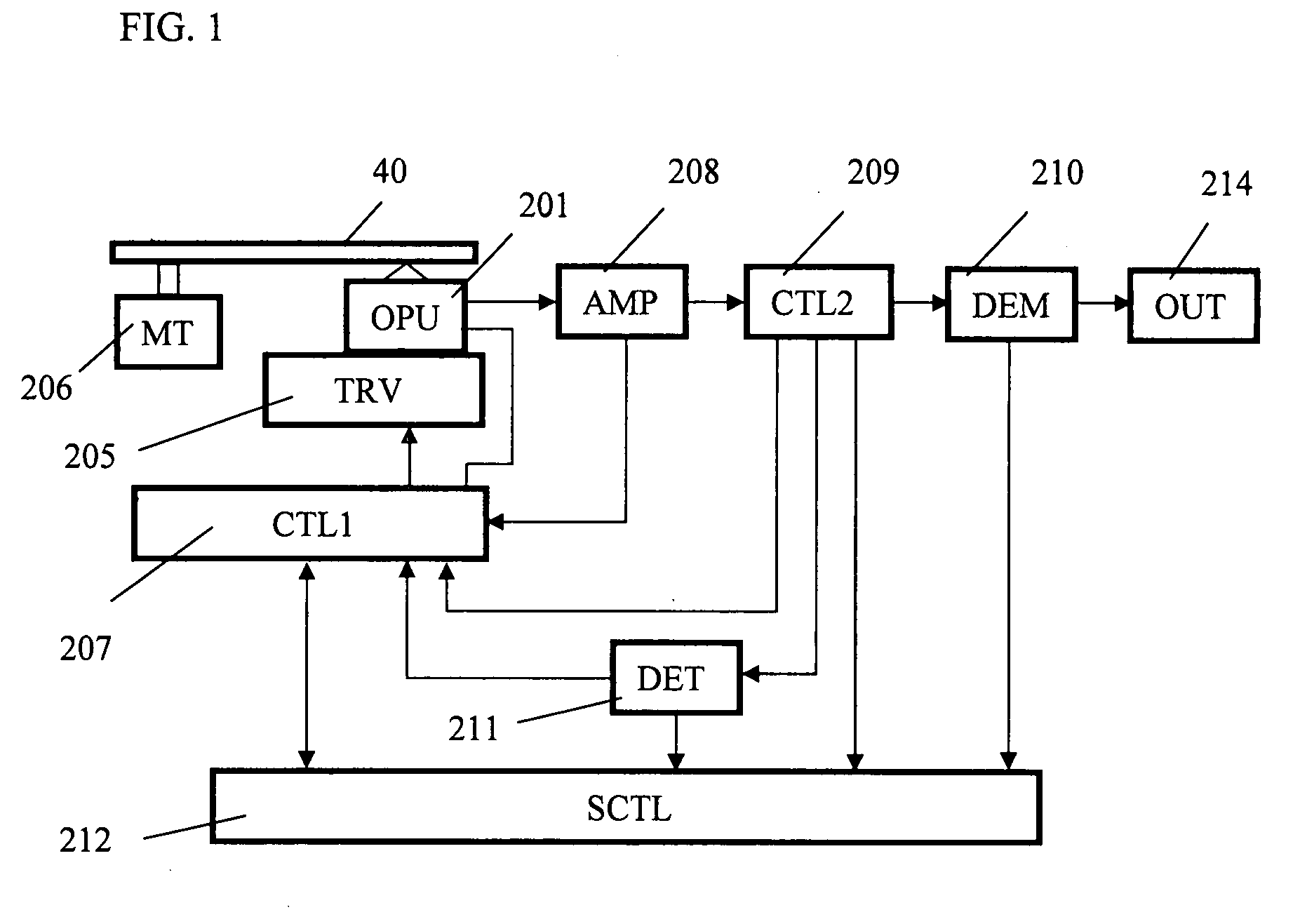
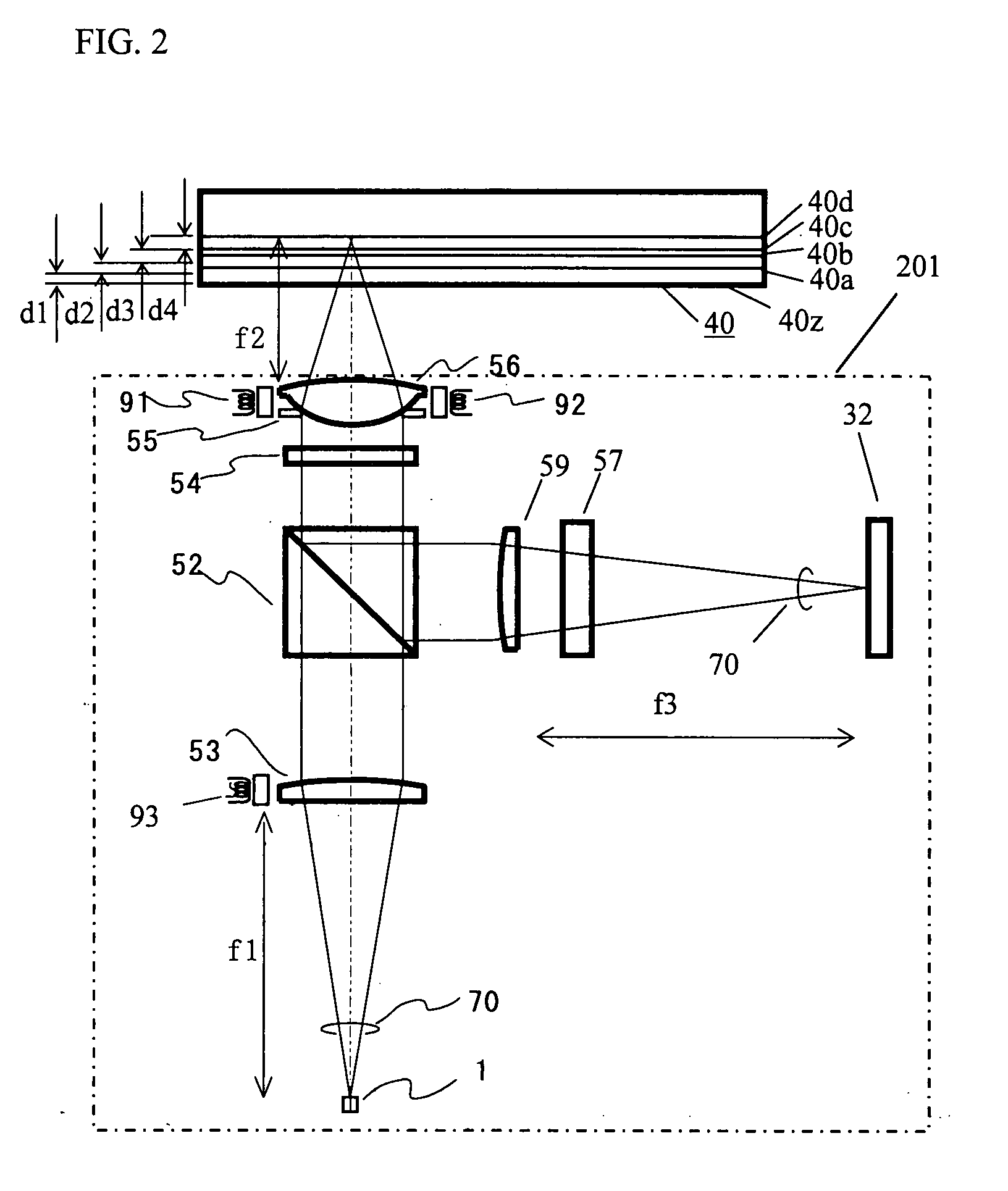
[0086]A first embodiment of the invention will be described hereinbelow with reference to FIGS. 1 and 2.

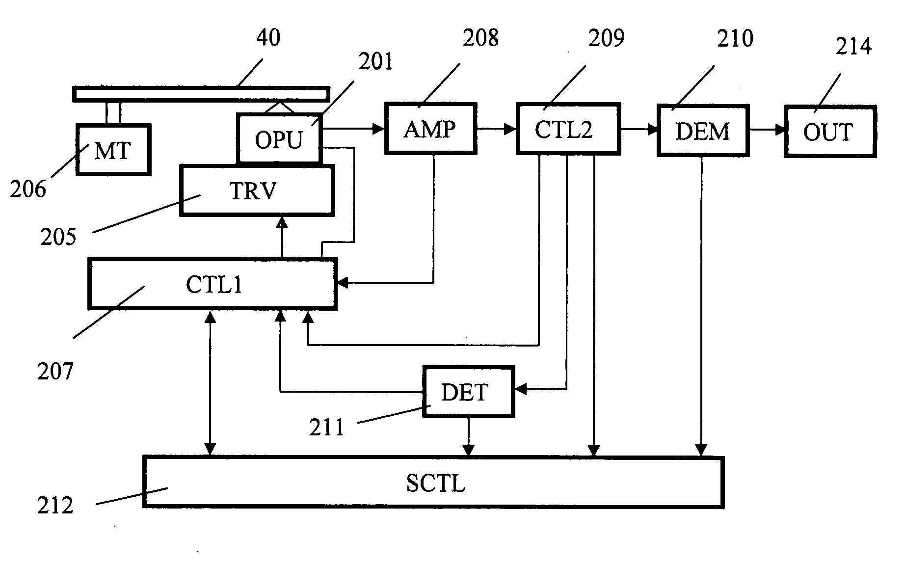
[0087]FIG. 1 shows the configuration of an optical information apparatus according to the invention. An optical pickup head apparatus 201 (also called an optical pickup) emits a laser beam having a wavelength λ of 405 nm to an optical recording medium 40, and reproduces a signal recorded on the optical recording medium 40. A transport controller 205 moves the optical pickup head apparatus 201 along the radial direction of the optical recording medium 40 in order to record / reproduce information in an arbitrary position on the optical recording medium 40. A motor 206 for driving the optical recording medium 40 rotates the optical recording medium 40. A controller 207 controls the optical pickup head apparatus 201, the transport controller 205, and the motor 206.

[0088]An amplifier 208 amplifies a signal read by the optical pickup head apparatus 201. An output signal from the amplifie...

second embodiment

[0098]FIG. 4 is a diagram showing an example of the configuration of an optical recording medium 41 according to a second embodiment.

[0099]In the first embodiment, it is the precondition that the thickness dhμm between the information recording faces is constant. Consequently, to control the light amount ratio of Sb as unnecessary light to Sb including an inherently necessary information, the transmittance th of the protection layer between the information recording faces of the optical recording medium and the reflectance αh of each of the information recording faces are set. In this case, however, flexibility of the transmittance th and the reflectance αh is regulated. In the second embodiment, by changing the thickness dhμm between neighboring information recording faces, flexibility in setting of the transmittance th and the reflectance αh can be increased. For example, in the case of recording / reproducing information to / from an information recording face 41d in the optical reco...

third embodiment

[0100]In the second embodiment, the conditions under which the focus fluctuation amount becomes 10% or less are calculated by the thickness difference between the neighboring base materials (dh−d(h−1)), concretely, (d4−d3) and the light quantity ratio Sb / Sd of Sb as unnecessary light to Sd including an inherently necessary signal. In a third embodiment, also in the case where there is no base material thickness difference, that is, in the case where the base material thickness dh between the signal recording faces is almost constant, by changing the refractive index of the base material between the signal recording faces, similar effects can be obtained. In this case, when the thickness between the signal recording faces is dμm and the refractive index of the base material between the signal recording face “h” and the signal recording face “h−1” is nh, by setting the transmittance th, reflectance αh, and the refractive index nh so as to satisfy the relation of ((α(h−1)2×α(h−2)) / (th2...


PUM

PropertyMeasurementUnit
distances d1aaaaaaaaaa
thickness toleranceaaaaaaaaaa

Abstract

The present invention provides an optical information medium capable of suppressing the influence of reflection light from an unnecessary information recording face and effectively eliminating spherical aberration at the time of recording / reproducing information to / from a recording medium having a plurality of information recording faces. When reflectance of an information recording face is αh and transmittance between information recording faces is th, ah and th of the optical information medium are set so as to satisfy ((α(h−1)2×α(h−2)) / (th2×αh))<0.01.

Description

FIELD OF THE INVENTION[0001]The present invention relates to an optical recording medium to / from which information is recorded / reproduced by being irradiated with light, a method for recording / reproducing optical information, and an apparatus for recording / reproducing optical information.BACKGROUND ART[0002]There are commercial optical disks called DVD and BD as high-density, large-capacity optical information recording media. Such optical disks are being rapidly spread recently as recording media for recording images, music, and computer data. An optical disk having a plurality of recording layers as shown in Japanese Unexamined Patent Publication No. 2001-155380 to further increase the recording capacity has been also proposed.[0003]FIGS. 19 and 20 show the configuration of a conventional optical recording medium and a conventional optical pickup.[0004]First, FIG. 19 will be described. An optical recording medium 401 in FIG. 19 has information recording faces 401a and 401b. Thickn...

Claims


Application Information

Patent Timeline
Patent Type & Authority Applications(United States)
IPC IPC(8): G11B3/74G11B7/24G11B7/24035G11B7/24038G11B7/243
CPCG11B7/24G11B7/2463G11B2007/0013G11B7/249G11B7/248
Inventor ANZAI, JOJIKADOWAKI, SHINICHIKAJINO, OSAMUMOHRI, MASANARI
Owner PANASONIC CORP
Learn More