
Thermogenerator to remediate contaminated sites

a technology of contaminated sites and thermal energy, applied in the direction of separation processes, insulation, borehole/well accessories, etc., can solve the problems of reliability problems, high cost of forming steam using electricity, and loss of heat of combustion resulting from incineration process, so as to reduce equipment required, reduce the cost of energy, and reduce the makeup fuel or energy required

Active Publication Date: 2009-01-29
VAST HLDG LLC
View PDF12 Cites 1 Cited by
  • Summary
  • Abstract
  • Description
  • Claims
  • Application Information

AI Technical Summary

Benefits of technology

[0018]A major portion of solid non-combustible pollutant components delivered to the combustor are removed after combustion and / or are extracted from any portion of the exit stream that is not delivered to the contaminated site. VAST combustion systems as described above, are very efficient, and the exit stream exhibits very low levels of CO and NOx, and pollutant components from the contaminated site. Any portion of the combustor exit stream which is not delivered to the remediation site is therefore capable of being safely released into the environment in compliance with legislative and / or regulatory requirements.
[0019]The hot extraction fluid delivered to the contaminated site typically heats up the contaminants, making them less viscous and therefore more mobile, facilitating extraction of the contaminated fluid.
[0023]Reuse of a portion of the reactor system exit fluid in the remediation process beneficially reduces the makeup fuel or energy required. It also reduces the equipment required.
[0024]Where a combustion process is employed, use of the VAST combustion system identified above is preferred, because it can operate efficiently using fluids with a high water content. Thus, effluent streams with high ratios of water to combustibles (whether in liquid or gaseous form), may be recovered from the contaminated site and processed directly without the need to separate out the water.
[0025]According to a sixth aspect of the invention, utilization of reactive components of the polluted effluent fluid significantly reduces the cost for energy required for generation of the extraction fluid, and may even enable reprocessing contaminant hydrocarbons into a marketable product, (e.g., as a fuel for use off site) where not all the reactive components of the effluent fluid are required to power the remediation process itself. Alternatively, the excess energy available can be used to do mechanical work on site. For example, a combustor can provide an energetic product fluid to drive a turbine to drive a compressor and or generate electricity for use on site or for sale. At the same time, destruction of the contaminants on site eliminates transportation costs and very high off site treatment or disposal costs.

Problems solved by technology

Forming steam using electricity is expensive, so steam is commonly generated using a standard Heat Recovery Steam Generator (HRSG) unit.
The heat of combustion resulting from the incineration process is typically lost.
All of these technologies have one or more disadvantages such as complexity leading to reliability problems, high cost, and occupation of large areas.
For example, producing the steam needed for the recompression process requires further equipment such as heat exchangers, pumps, compressors, with major quantities of energy needed operate this additional equipment.
This increases operating and capital costs, and equipment footprints, while reducing efficiencies.

Method used


Image

  • Thermogenerator to remediate contaminated sites
  • Thermogenerator to remediate contaminated sites
  • Thermogenerator to remediate contaminated sites

Examples


Embodiment Construction

General:

[0038]In the description which follows, the pollutants are assumed to include a substantial quantity of combustible hydrocarbons, and the primary energy generation process will be a combustion process. As such, the presently known best mode of practicing the invention utilizes the VAST combustion system described in the above-identified patents, the invention will be described in that context. It should be understood, however, that other reaction systems and processes capable of generating the needed remediation fluid, and of converting the extracted contaminant into a safely disposable form can alternatively be employed.

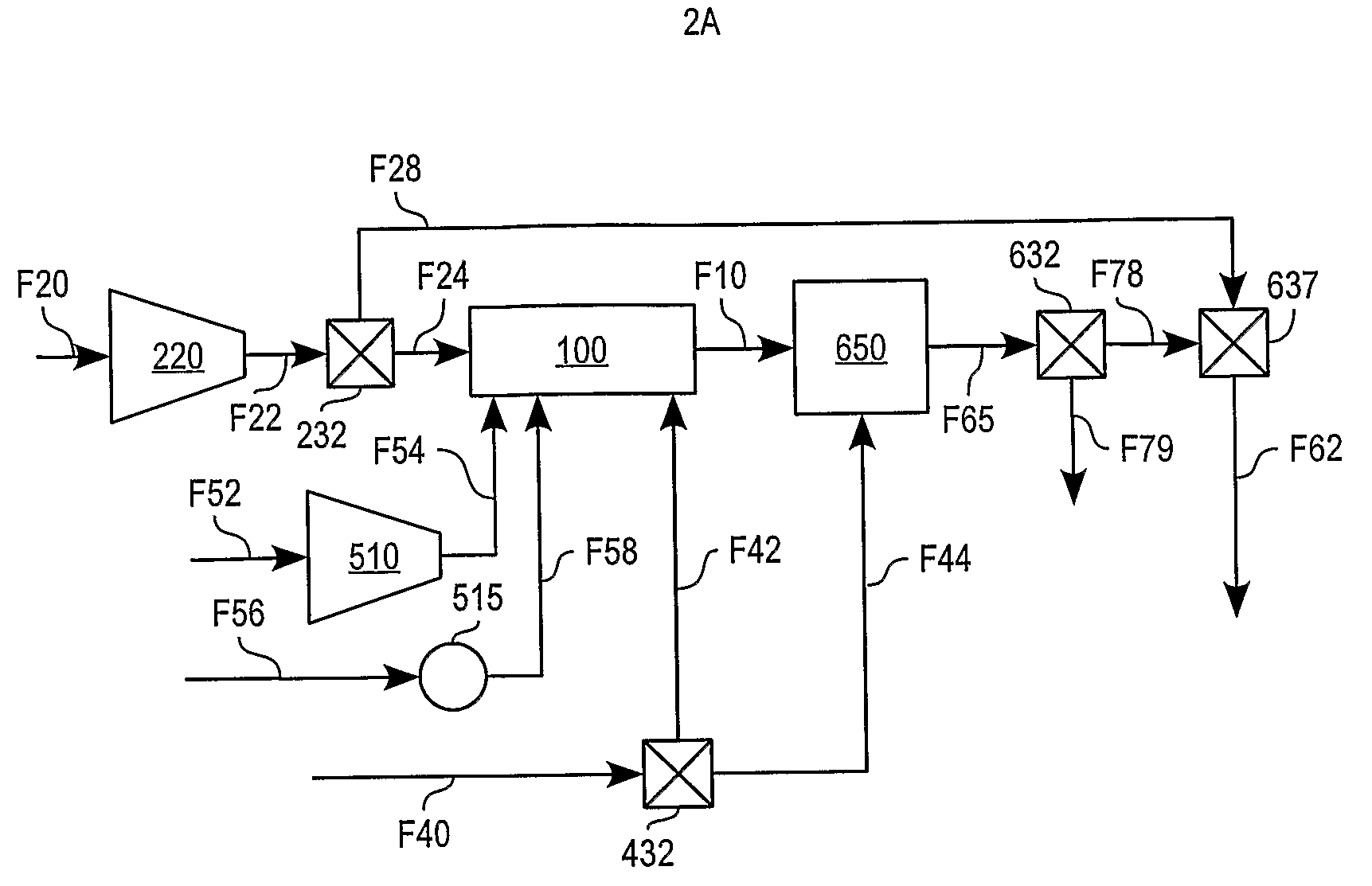
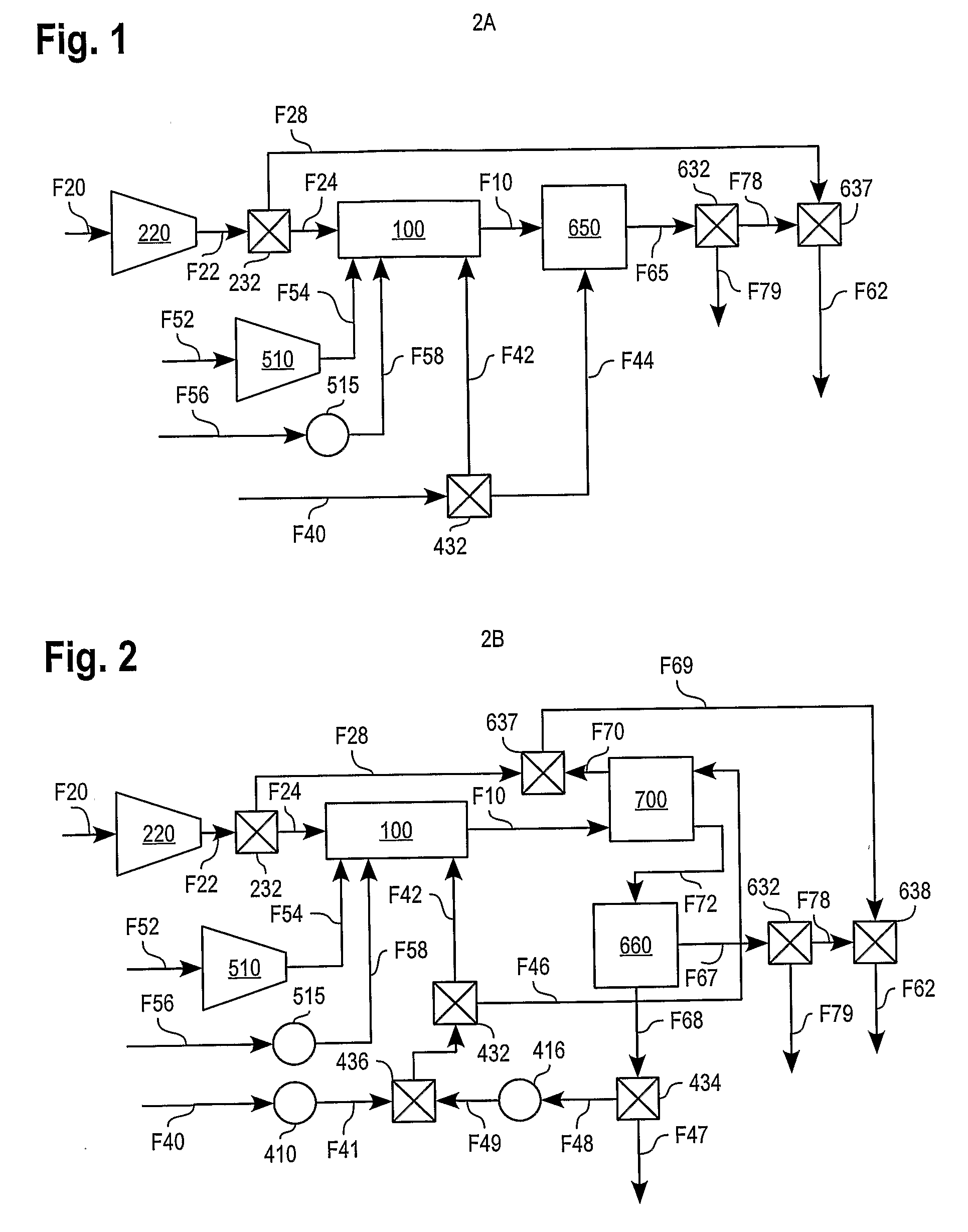
[0039]Turning now to FIG. 1, a remediation system according to the invention, generally denoted at 2A, provides remediation fluid F62 for delivery into the ground within or near the contaminated site. Remediation fluid F62 comprises products of combustion and preferably includes steam. It optionally includes a steam-air combination, and optionally liquid wat...


PUM


Abstract

A remediation system and method for decontaminating a polluted site. An outlet system is to deliver a remediation fluid to the polluted site, and an inlet system receives a contaminated effluent from the polluted site. A processing system extracts a contaminant component from the contaminated effluent. A reactor receives the extracted contaminant component as a first reactant, and also, a second reactant. The reactor generates a reaction product-containing exit fluid stream, a controlled portion of which is released from the system. The remaining portion of the reactor exit fluid forms the remediation fluid. Optionally, the remaining portion is combined with a controlled quantity of the second reactant to form the remediation fluid. In addition, a controlled quantity of diluent / coolant fluid may be delivered into a reaction process in the reactor and / or downstream of the reaction process, and / or separately in a heat transfer system. This cools the exit fluid, and the diluent / coolant becomes part of the remediation fluid. Where the pollutants are combustible, the reactor is a combustor, and the diluent is water, which adds to the steam, which is generated by the combustion process.

Description

PRIORITY INFORMATION[0001]This application is based on and claims benefit of U.S. Provisional Patent Application No. 60 / 661,985, filed Mar. 14, 2005, entitled THERMOGENERATOR TO REMEDIATE BROWNFIELD CONTAMINATION, Provisional Application 60 / 728,915, filed Oct. 21, 2005, entitled THERMOGENERATOR TO REMEDIATE BROWNFIELD CONTAMINATION and Provisional Application 60 / 772,716 filed Feb. 13, 2006, entitled THERMOGENERATOR TO REMEDIATE CONTAMINATION, the disclosures of which are hereby incorporated by reference and to which a claim of priority is hereby made.BACKGROUND OF THE INVENTION[0002]1. Field of the Invention[0003]The invention relates in general to methods of remediating a contaminated site and of destroying contaminants.[0004]2. Description of the Related Art[0005]Currently steam is being used to clean up contaminated or remediation sites. FIGS. 9 and 10 show a common configuration of a current art treatment system, in this case the system used to clean up a NASA site at Cape Canav...

Claims


Application Information

Patent Timeline
IPC IPC(8): B09C1/02B09C1/06F02C3/20
CPCB09C1/00B09C1/06B09C1/02
Inventor GOHEEN, BILLKLAUS, RONALD L.HAGEN, DAVID L.GINTER, GARYMCGUIRE, ALLENNAYLOR, TIMOTHY
Owner VAST HLDG LLC
Learn More