Control device for watercrafts

a control device and watercraft technology, applied in mechanical control devices, controlling members, shafts, etc., can solve problems such as malfunctions, stop the transmission of command signals, and certain drawbacks, so as to reduce the use of the bus, reduce the transfer speed and accuracy of signal transmission, and reduce the effect of check actions

Inactive Publication Date: 2009-01-29
ULTRAFLEX
View PDF11 Cites 3 Cited by
  • Summary
  • Abstract
  • Description
  • Claims
  • Application Information

AI Technical Summary

Benefits of technology

[0036]The digital signal is transmitted to the actuator through the digital transmission line, generally a BUS, preferably a CanBUS. A digital signal intended to transfer only a piece of information contained in the main command signal set by the control lever uses a very small number of bits, for example, a digital command signal that is intended to transmit only the command signal engaging a gear can be of only 4 bits / second and uses a very thin band with respect to the overall band of the BUS. Advantageously, a simplified CanBUS may be employed and / or said BUS may be overcharged to a smaller extent. Because errors are less frequent, the use of the BUS is reduced, obtaining a considerable increase in transfer speed and accuracy of the signal transmission, with fewer check actions.
[0037]A further advantage of a device according to the present invention resides in the simplified control electronics. Hardware or software for correcting errors during the transfer of command signals can be advantageously reduced with respect to a completely electronic device, since the amount of information to be checked is significantly reduced, and, in comparison with known electronic devices, goes from 64 to 4 bits / second. Therefore, hardware or software for checking errors that typically monitors the transmission of digital signals, for example, suitable software or not volatile memories, can be considerably simplified, leading to reduced costs while still maintaining the advantages of an entirely digital transmission.
[0038]The analog command signal instead is most suitable for transmitting the signal related to the position and / or the angular displacement of the control lever, since such signal is a progressive signal indicating the position or the progressive displacement of the lever, in opposition to the set gear signal, which is a discrete signal and possibly a on / off signal. Therefore, the analog transmission line is particularly advantageous in transmitting said type of command signal and has considerable advantages in comparison to mechanical or electromechanical devices, requiring less maintenance, and is also safer when compared thereto.

Problems solved by technology

These types of merely mechanical control devices are inexpensive but suffer from certain drawbacks.
Operation, above all in middle-sized watercrafts where the mechanical cable has a considerable length, requires a considerable force on the control lever, moreover, due to assembling and operating tolerances, the command signal is inaccurately transmitted.
Other drawbacks are due to the fact that in marine applications a mechanical cable is easily subjected to incrustation, causing malfunctions and / or the transmission of the command signal to be stopped.
Moreover, a mechanical cable needs frequent maintenance, above all in an aggressive environment such as the marine environment, causing the user to provide an expensive maintenance.
The installation of a device of this kind is also complicated and expensive.
Today, such a merely mechanical device is becoming outdated and it is typically mounted only onto very small-sized and economic watercrafts.
Due to these drawbacks, such electromechanical control devices are not recommended for middle-sized and middle-cost watercrafts, and are more preferably used on economic and small-sized watercrafts.
A first drawback of this type of device is related to cost.
A control unit configured to change a series of signals deriving from one or more sensors into corresponding digital command signals to be sent by a digital BUS is relatively expensive, because the signals to be changed and checked are numerous and concern the progressive position of the lever and the gear set or to be set.
In some cases, it is necessary for the checking software to be loaded in a no volatile memory, which is typically integrated into the unit, thereby increasing cost, complexity and sensitivity to damages or malfunctions.
In this second case, the control device uses the BUS to a considerable degree and causes the speed of data transmission to increase and / or may cause error when transmitting data, so a suitably sized BUS must be employed, which is more expensive.
This requires alternatively the use of a communication BUS able to stand a large amount of data, which is expensive, or the use of various communication BUSes, and, in an undesirable scenario, a BUS dedicated for each piece of equipment, with considerable drawbacks as far as costs and mounting problems are concerned.
As it can be seen, even if the merely electronic device of prior art can overcome drawbacks of the merely mechanical or electromechanical devices, a merely electronic device, in which data are transmitted only as digital signals, has a mounting cost that is considerably higher than for the other two above described types of control devices, and is suitable for the use only in large-sized and correspondingly expensive watercrafts.
The cost of such a merely electronic device for middle-sized watercrafts it is often too high in relation to the cost of the watercraft itself.
With regard to reliability and to the consequences of an error in transmitting the command signal, the heavy damages should be considered that would occur, for example, during mooring if the transmission of the command signal has errors or deviations with respect to what had been set and desired by the user acting on the control lever, and the dangerous condition should also be considered that could derive from a systematic error of the control system.

Method used


Image

  • Control device for watercrafts
  • Control device for watercrafts
  • Control device for watercrafts

Examples


Embodiment Construction

[0050]Detailed descriptions of embodiments of the invention are provided herein. It should be understood, however, that the present invention may be embodied in various forms. Therefore, the specific details disclosed herein are not to be interpreted as limiting, but rather as a representative basis for teaching one skilled in the art how to employ the present invention in virtually any detailed system, structure, or manner.

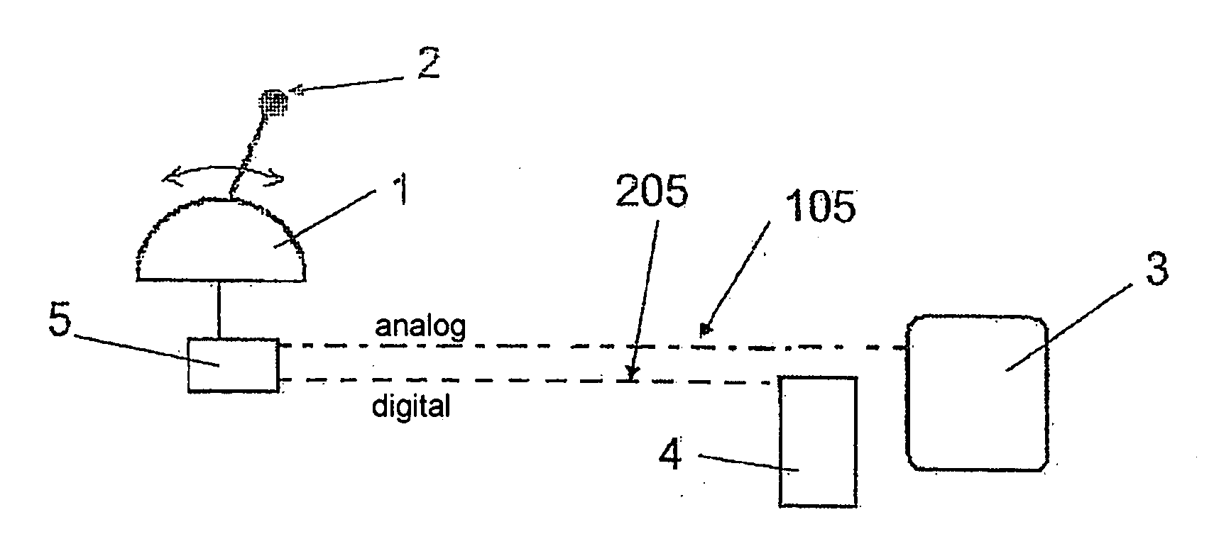
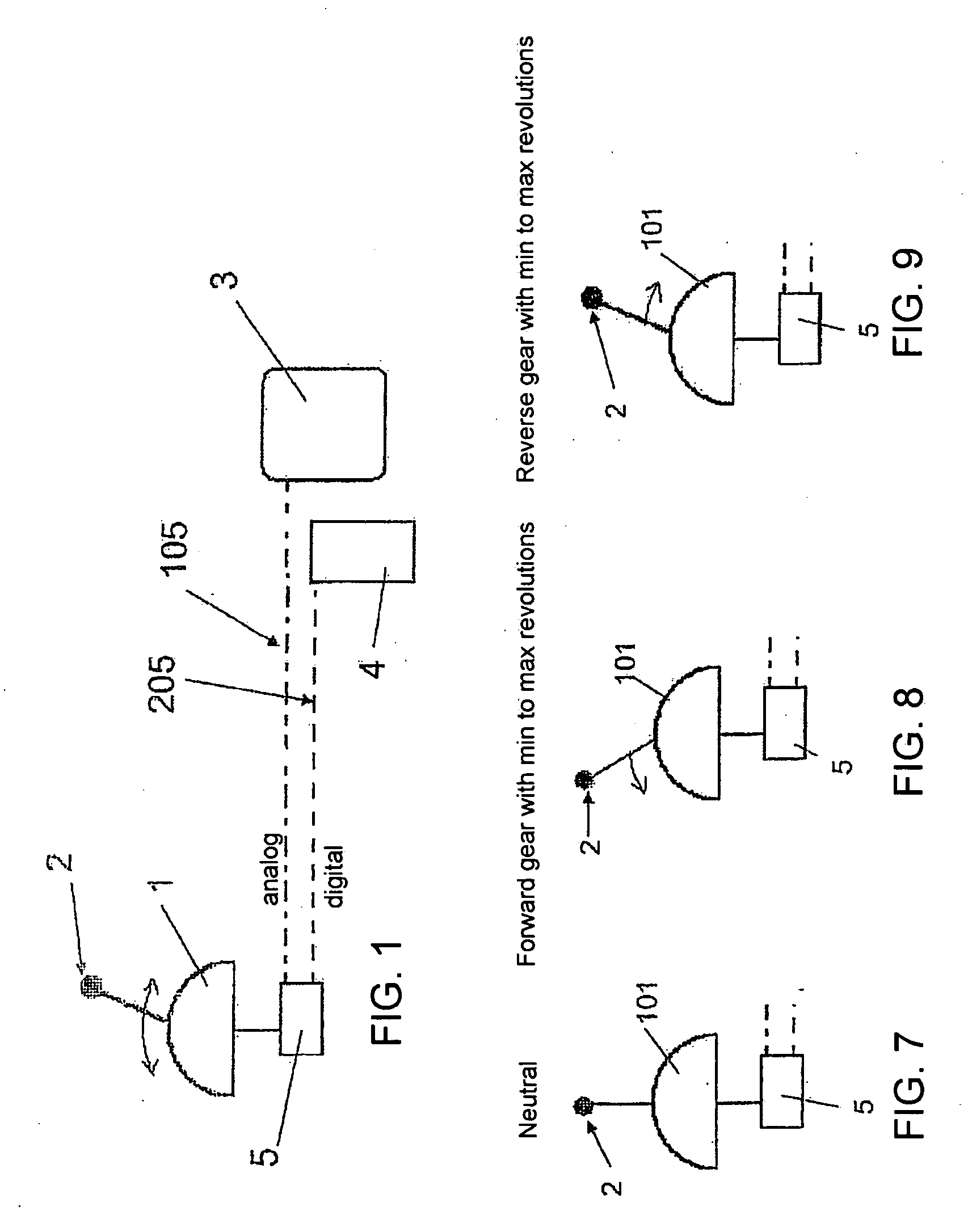
[0051]FIG. 1 is a preferred embodiment of a control device for watercrafts according to the present invention, particularly for watercrafts that include at least a control station 1 provided with at least a control lever 2, a motor 3, and an actuator 4 coupled to motor 3.

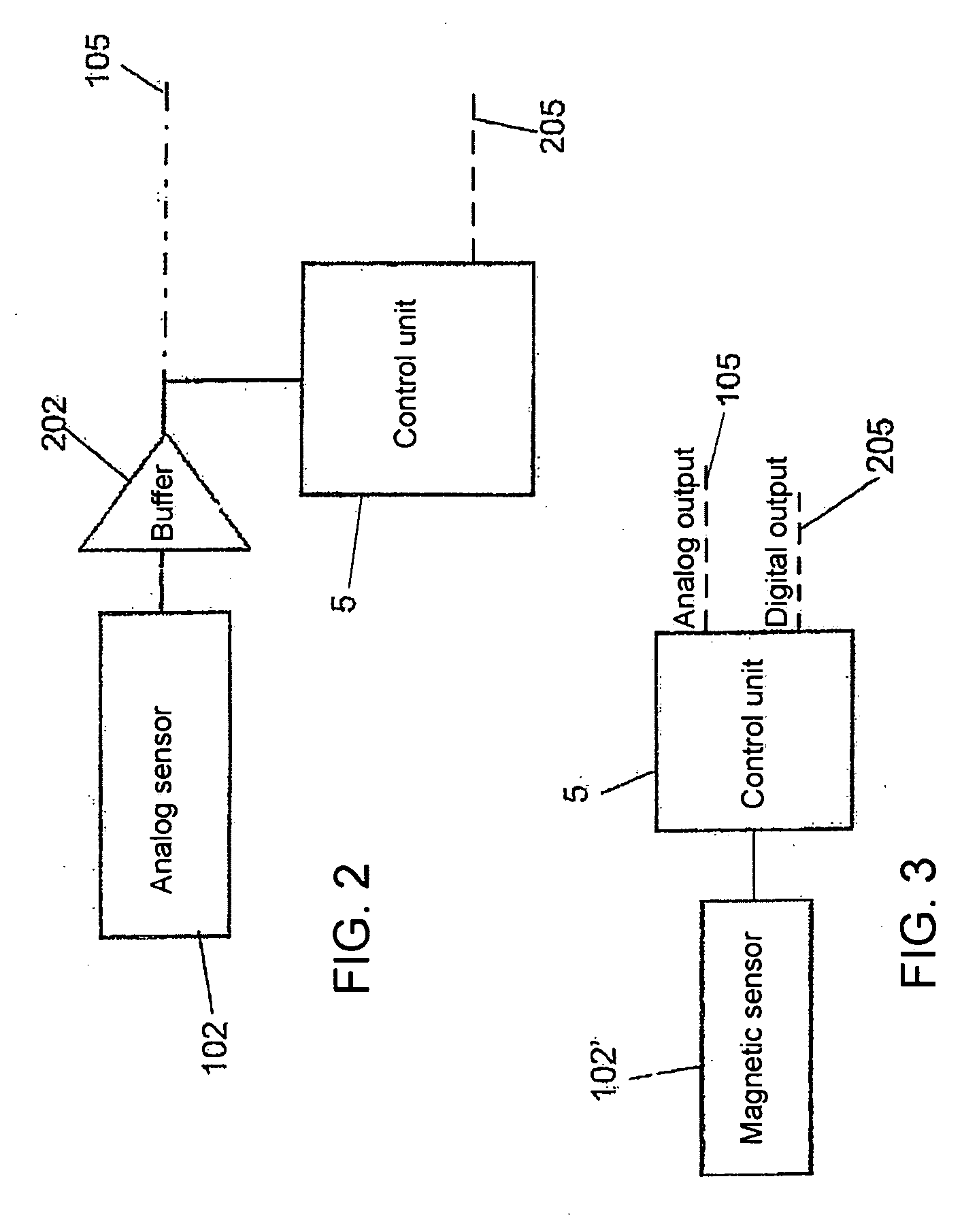
[0052]Control lever 2 is provided with one or more sensors for detecting a main command signal that can be set by control lever 2.

[0053]Lever 2 is operated by a user, typically for controlling motor or motors 3 of the watercraft. Inputs set by the user by a single lever 2 relate to gear and numbe...


PUM


Abstract

A control device for watercrafts includes a control station having a control lever, a motor, and an actuator coupled to the motor. In one embodiment, the control lever is provided with a sensor for generating a main command signal that corresponds to or is related to a position and/or a displacement of the control lever. The control device further includes control electronics receiving as input at least the main command signal and further having at least a first analog transmission line and a second digital transmission line for transmitting command signals. The control electronics divide the main command signal in two different command signals, a first analog command signal and a second digital command signal, the first analog command signal being sent to the motor through the analog transmission line and/or the second digital command signal being sent to the actuator through the second digital transmission line.

Description

FIELD OF THE INVENTION[0001]The present invention relates to a control device for watercrafts that includes a control station, a motor, and an electromechanical actuator coupled to the motor. The control device of the present invention is employed for transmitting a command signal from a control station to an electromechanical actuator, typically but not exclusively coupled to the motor of the watercraft.[0002]A control station according to the present invention may include a control member, such as a lever, which provides a command signal derived from, or corresponding to, the position and / or displacement of the control member in relation to a specific range and to a specific initial position of the control member, and more particularly to the position and / or displacement thereof. The command signal may be directly sent to the motor by an analog signal, typically a potential difference, acting in turn on a control member of the motor.[0003]In the following description and claims, f...

Claims


Application Information

Patent Timeline
Patent Type & Authority Applications(United States)
IPC IPC(8): B63H21/21G06F17/00
CPCB63H21/213F02D41/28Y10T74/20456Y10T74/20462Y10T74/2045G05G1/04
Inventor GAI, GIORGIOBOSIA, GIORGIO
Owner ULTRAFLEX
Why Eureka
Try Eureka