Method and apparatus for a product dispenser with increased insulative properties

a product dispenser and insulative property technology, applied in the field of product dispensers, can solve the problems of losing sales, not always providing an equivalent thermal solution, and product dispenser manufacturers no longer being able to utilize foam blowing agents, etc., and achieve the effect of increasing insulative properties and increasing thermal efficiency

Inactive Publication Date: 2009-02-05
LANCER PARTNERSHIP
View PDF5 Cites 64 Cited by
  • Summary
  • Abstract
  • Description
  • Claims
  • Application Information

AI Technical Summary

Benefits of technology

[0008]In accordance with the present invention, a product dispenser includes at least one vacuum insulation panel disposed around a vessel of the product dispenser, such that a chamber disposed within the vessel has an increased thermal efficiency. In a first embodiment, the product dispenser includes a first layer of vacuum insulation panels disposed adjacent to the exterior walls of the vessel to substantially encapsulate the vessel, thereby providing increased insulative properties to the chamber that houses a product. The product dispenser may further include additional layers of insulation disposed over the first layer. A subsequent layer of insulation may be constructed from additional vacuum insulation panels or an as-formed foam insulation, thereby providing a composite thermal solution.
[0009]The vacuum insulation panels provide any type of vessel of a product dispenser with increased insulative properties. Illustratively, the composite insulation may be applied to a product chamber, vessels for ice water baths, refrigerated cabinets, and the like. The increased thermal efficiency of the vessel provides an extended thermal equilibrium profile, as less energy is dissipated per unit time. The increased thermal efficiency further provides for reduced run time for the product dispenser, as refrigerated chambers remain colder for longer periods.

Problems solved by technology

Product dispenser manufacturers must comply with the new design standards or lose sales.
Illustratively, product dispenser manufacturers are no longer able to utilize HFC blowing agents for foams, and the simple substitution of a foam blowing agent does not always provide an equivalent thermal solution.
Further complications arise because the product dispenser is already designed and in production.
As such, foam substitutions for a blown in place foaming operation that cures around components disposed in the foaming cavity will, most likely, require a blown in foam solution, as a modular form of the foam would not fit into areas with existing components.
Further, not all variables of similar type arrangements may be manipulated.
For example, increasing a thickness of a less-efficient foam substitution is not acceptable, as existing components often fit around a pre-existing foam thickness.
The reworking of the mating components would be a costly endeavor, as multiple components would be affected, each of which includes design considerations, tooling considerations, planning considerations, and the like.

Method used


Image

  • Method and apparatus for a product dispenser with increased insulative properties
  • Method and apparatus for a product dispenser with increased insulative properties
  • Method and apparatus for a product dispenser with increased insulative properties

Examples


first embodiment

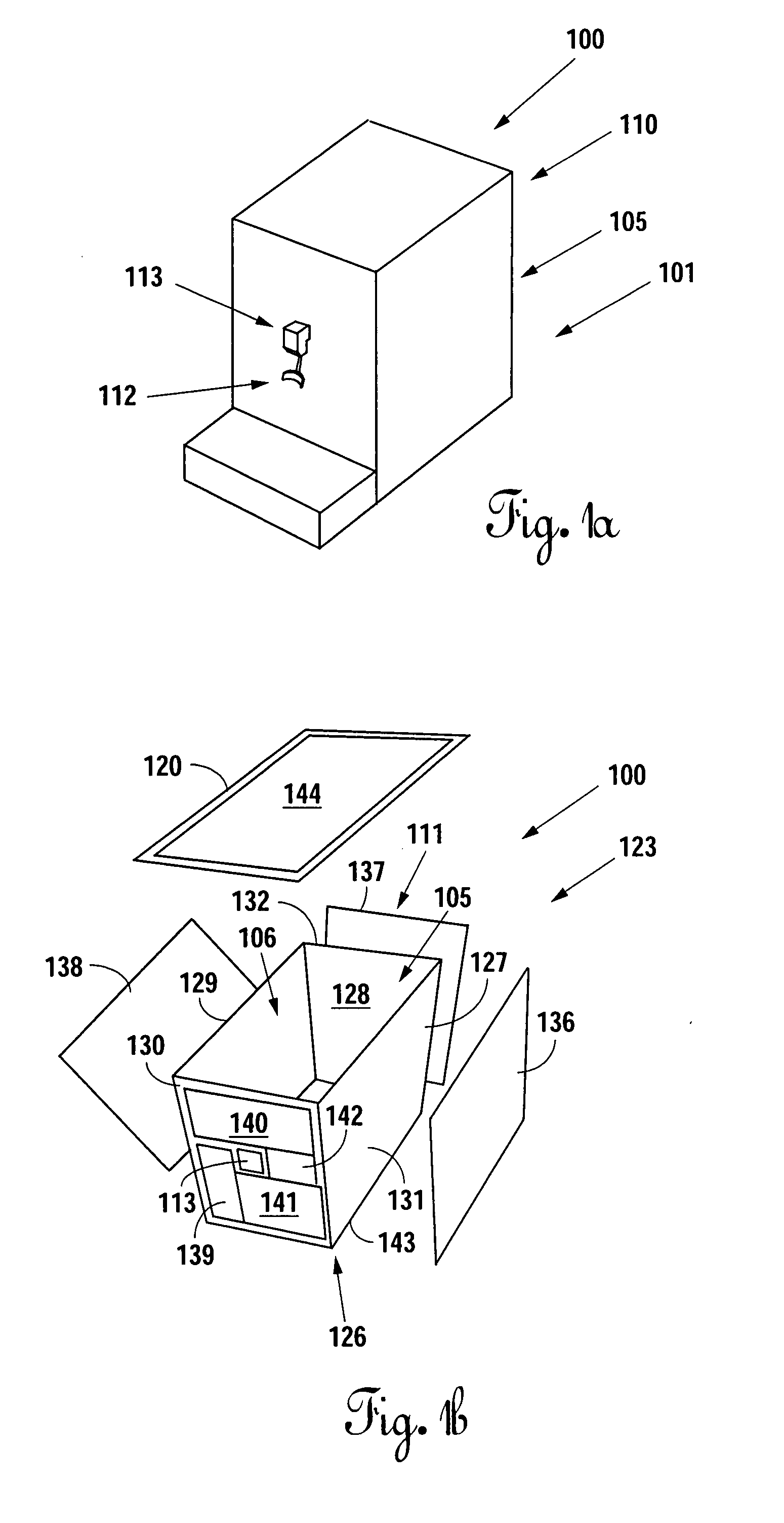
[0034]In a simplest form, a product dispenser 100 includes a housing 110, and at least one product flow circuit 101 for receiving a product and dispensing the product. The housing 110 includes a vessel 105 supported by a frame assembly. The frame assembly provides structural support to the components of the product dispenser 100, and may be constructed from virtually any form of structural member made from commonly available structural materials, including steel, aluminum, plastics, and the like. In this first embodiment, the frame assembly is a welded steel frame.

[0035]The vessel 105 may be any form of product containment device, including tanks, bins, liners, and the like, that includes or forms a chamber 106. The vessel 105 may be constructed from virtually any form of material that is structurally adequate to contain and support a chamber 106 full of a particular product. In this first embodiment, the vessel 105 is a liner formed from polypropylene. At a minimum, the vessel 105 ...

second embodiment

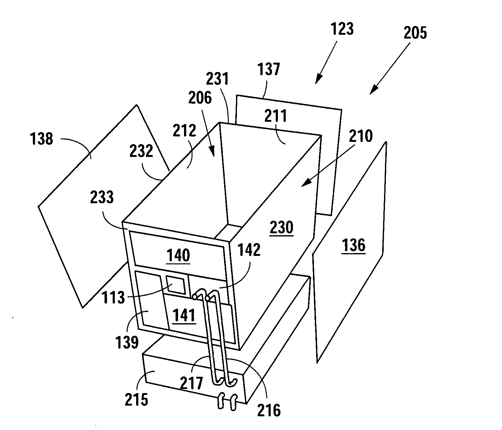
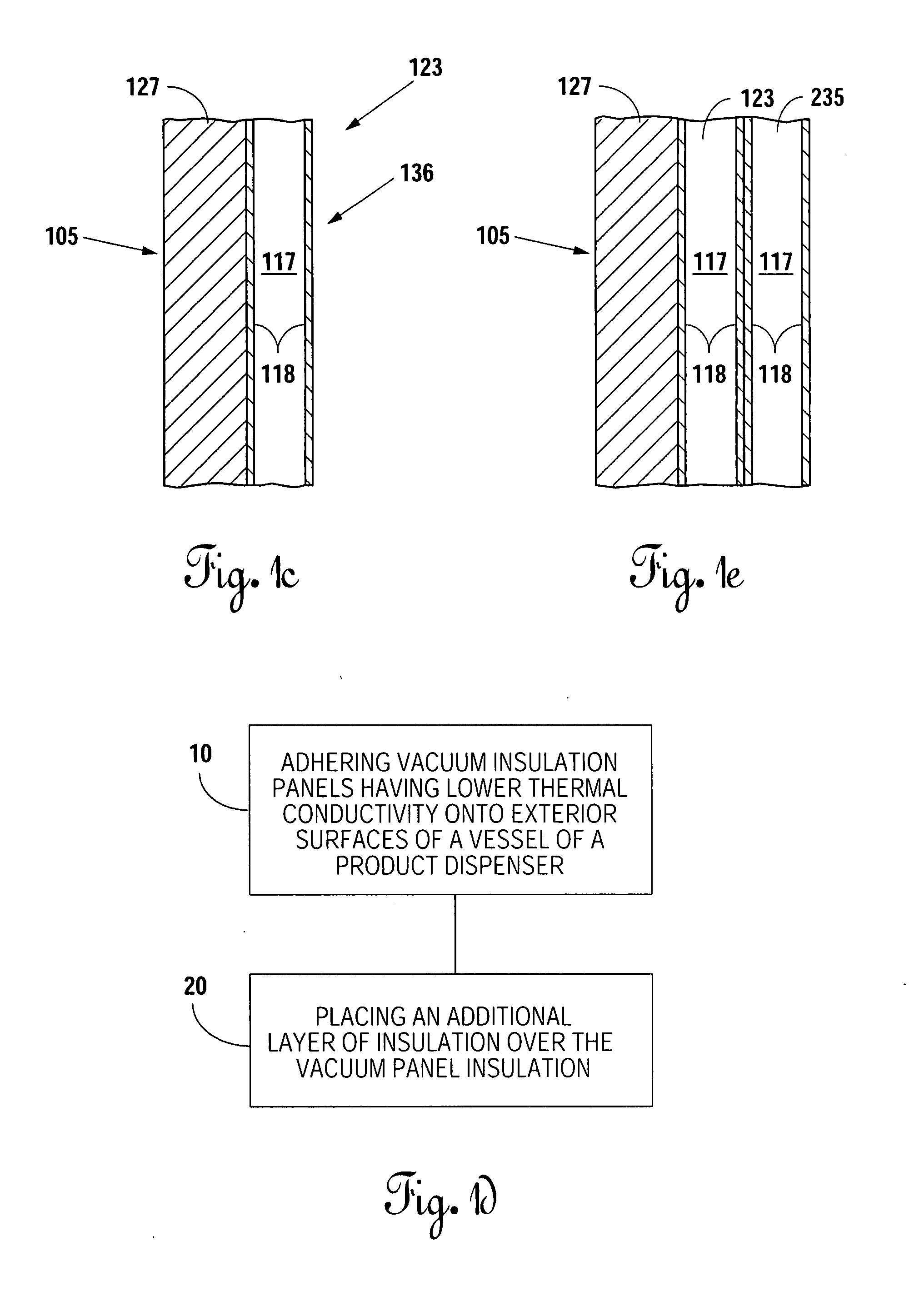
[0056]In an extension of the second embodiment, the product dispenser 200 may further include a second layer of insulation 235 disposed over the first layer of vacuum insulation panels. The second layer of insulation 235 may be a second layer of vacuum insulation panels, or may be a layer of as-formed foam insulation 151. As shown in FIG. 3c, an as-formed foam insulation 151 is identical to that of the product dispenser 150. The as-formed foam insulation 151 permanently locates and supports any product lines disposed around the vessel 205, and creates a composite insulation platform, identical to that shown in FIG. 2b. The increased thermal properties provide an increased thermal efficiency for the chamber 206.

third embodiment

[0057]In a third embodiment, a product dispenser 250 includes a concentrate flow circuit 252, and a diluent flow circuit 253. The product dispenser 250 further includes a vessel 260 having a first wall 271, a second wall 272, a third wall 272, a fourth wall 274, and a floor panel 275 that form a chamber 261. The concentrate flow circuit 252 is connectable to a concentrate source, and includes at least one concentrate line 255. The diluent flow circuit 253 is similarly connectable to a diluent source, and includes at least one diluent line 256. At least one diluent line 256 and one concentrate line 255 pass through the chamber 261 of the vessel 260. The diluent line 256 and the concentrate line 255 may make multiple passes through the chamber 261 to provide adequate length for desired amount of heat transfer. The opposing ends of the diluent line 256 and the concentrate line 255 are then connectable to a product valve for dispensing.

[0058]The product dispenser 250 further includes a ...


PUM

PropertyMeasurementUnit
thermal conductivityaaaaaaaaaa
thermal efficiencyaaaaaaaaaa

Abstract

Vacuum insulation panels with a decreased thermal conductivity provide increased thermal effectiveness in a vessel of a product dispenser, when the vessel is substantially encapsulated with the vacuum insulation panels. The product dispenser including insulation having a reduced thermal conductivity provides the ability to convert existing manufacturer product lines from designs requiring foams with hydroflorocarbon blowing agents to foams that utilize non-hydroflorocarbon blowing agents. The vacuum insulation panels may be placed adjacent to the vessel walls, or may be adhered to the vessel walls. In an extension of this embodiment, multiple layers of vacuum insulation panels may be applied to the vessel to further increase the thermal effectiveness of the vessel. Still further, the layers of the vacuum insulation panels may be covered with an as-formed foam insulation, thereby creating a composite thermal barrier.

Description

BACKGROUND OF THE INVENTION[0001]1. Field of the Invention[0002]The present invention relates to product dispensing equipment and, more particularly, but not by way of limitation, to methods and an apparatus for increasing the insulative properties of product dispensers that include foam insulation.[0003]2. Description of the Related Art[0004]In the quest to be environmentally conscious, product suppliers are forcing product dispenser manufacturers to engage in their quest by placing new standards on orders for products on existing product lines. Product dispenser manufacturers must comply with the new design standards or lose sales. One new standard forces product dispenser manufacturers to remove components that utilize HFC's in the manufacturing process. While the substitution of HFC components with components that do not utilize HFC's in the manufacturing process may seem routine, one of ordinary skill in the art will recognize that the substitution of randomly selected componen...

Claims


Application Information

Patent Timeline
Patent Type & Authority Applications(United States)
IPC IPC(8): F25D23/00
CPCB67D2210/00044Y10T29/49826F25D2201/14F25D31/002
Inventor ROGALA, ALLEN L.HAWKINS, JOHN T.
Owner LANCER PARTNERSHIP
Why Eureka
Try Eureka