
Photocatalytic ignition system

a photocatalytic ignition and photocatalytic technology, applied in the field of photocatalytic ignition systems, can solve the problems of insufficient ability of existing photocatalytic materials to reduce the low efficiency of high-efficiency photocatalytic materials, and the inability to propose a practical photocatalytic ignition system, etc., to achieve the effect of high efficiency and reducing the minimum ignition energy

Inactive Publication Date: 2009-02-05
NISSAN MOTOR CO LTD
View PDF1 Cites 4 Cited by
  • Summary
  • Abstract
  • Description
  • Claims
  • Application Information

AI Technical Summary

Benefits of technology

[0013]As described above, an air fuel mixture igniting system that uses a photocatalyst brings the advantage of enabling the minimum ignition energy to be reduced because the radicals necessary for igniting the air fuel mixture can be produced comparatively readily at the surface of the photocatalyst. However, a highly effective photocatalytic material has not been proposed and the ability of existing photocatalytic materials to lower the minimum ignition energy is not sufficient. Consequently, a practical photocatalytic ignition system has yet to be proposed.
[0015]In accordance with one aspect, a photocatalytic ignition system is provided that basically comprises an ignition chamber, a photocatalyst and a light source. The ignition chamber is configured to receive an air fuel mixture. The photocatalyst is arranged in the ignition chamber to contact an air fuel mixture. The light source is arranged to shine light on the photocatalyst. The photocatalyst includes a photocatalytic material having an oxygen absorbing and a desorbing function. The photocatalytic ignition system is capable of igniting a lean air fuel mixture with a greatly reduced amount of light energy.

Problems solved by technology

However, a highly effective photocatalytic material has not been proposed and the ability of existing photocatalytic materials to lower the minimum ignition energy is not sufficient.
Consequently, a practical photocatalytic ignition system has yet to be proposed.

Method used


Image

  • Photocatalytic ignition system
  • Photocatalytic ignition system
  • Photocatalytic ignition system

Examples


working example 1

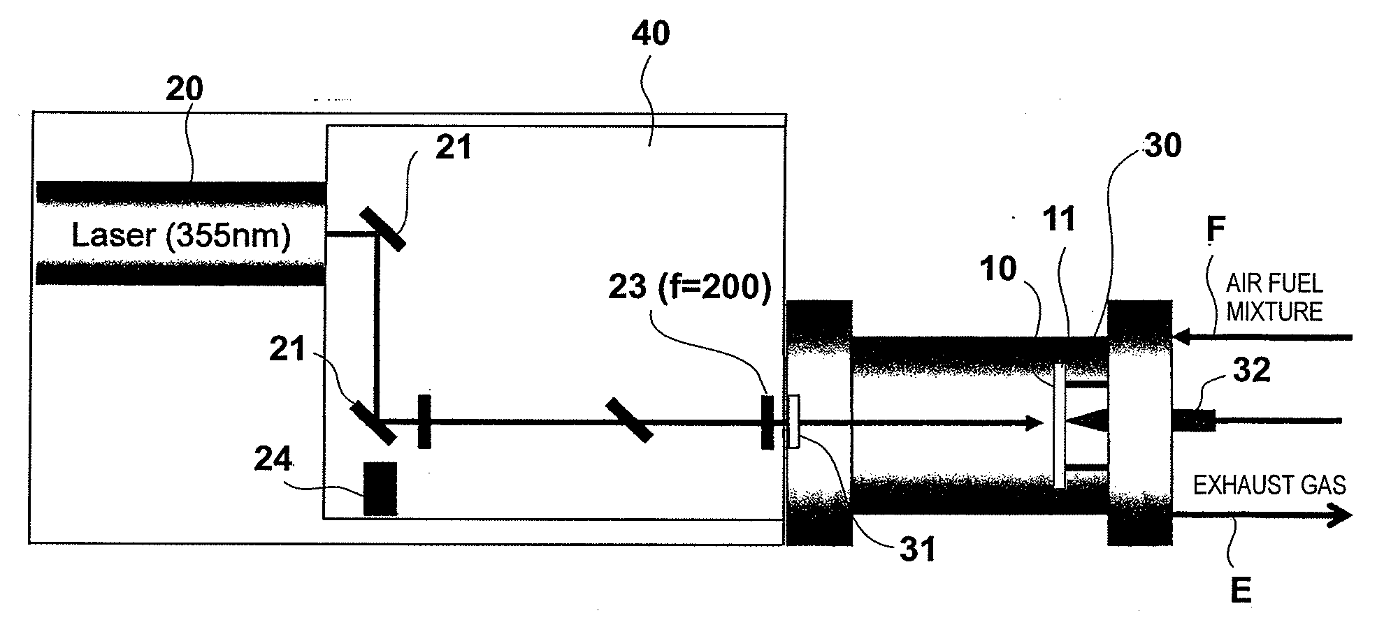
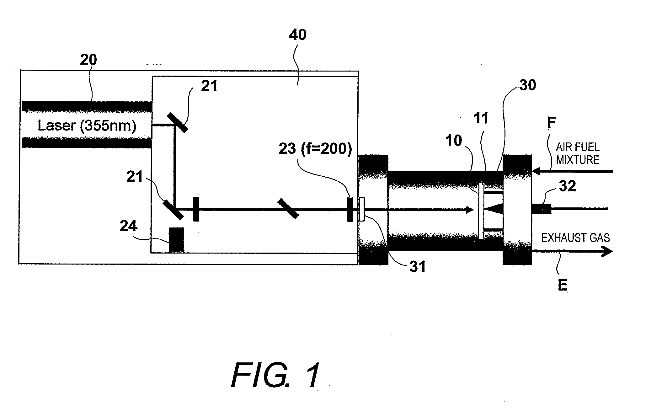
[0040]The photocatalytic ignition system shown in FIG. 1 was fabricated and the performance thereof was evaluated. The procedures of the fabrication and performance evaluation of the system will now be explained.

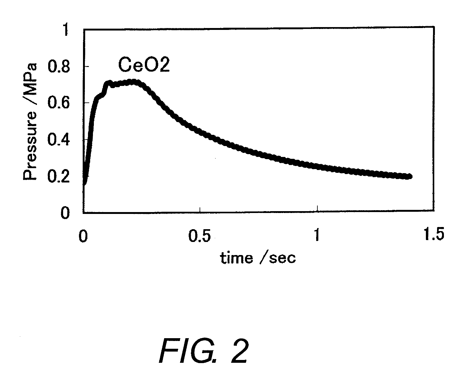
[0041]An aluminum plate having a diameter of 60 mm was used as the substrate plate 11. Oil was removed from the aluminum plate by treating it with alcohol and, afterwards, an inorganic adhesive (main ingredient: a alumina) was coated onto the aluminum plate. Next, the photocatalyst 10 was made by spraying cerium oxide sol having a particle size of 20 nm to a thickness of several micrometers and firing to remove moisture.

[0042]The laser light was provided by a Nd-YAG laser (355 nm) and pulsed at a pulse width of 5 to 7 nsec. The laser light was passed through a 355 nm wavelength separator mirror, an attenuator (½ wavelength plate and polarizer plate), a light collecting lens (f=200), and a quartz glass window and shone onto the photocatalyst inside the ignition chamber. A mix...

working example 2

[0044]An aqueous solution was prepared with ferric nitrate and cerium nitrate at a mole ratio of Fe to Ce (Fe / Ce) equal to 0.8 / 0.2. The solution was agitated one day and one night while gradually dripping in an aqueous solution containing 28% ammonia such that a pH of 8 was achieved. The resulting solid material was then filtered out, rinsed with deionized water, and heated to 600° C. for five hours to obtain Fe0.8Ce0.2. The Fe—Ce material was used as the photocatalyst. Otherwise, the same operations as were performed in Working Example 1 were repeated. Table 1 shows the minimum ignition energy (mJ) for the photocatalyst used in this working example.

working example 3

[0045]An aqueous solution was prepared with ferric nitrate and cerium nitrate at a mole ratio of Fe to Ce (Fe / Ce) equal to 0.2 / 0.8. Otherwise the same operations as were performed in Working Example 2 were repeated. The minimum ignition energy (mJ) is shown in Table 1.


PUM


Abstract

A photocatalytic ignition system is provided that basically comprises an ignition chamber, a photocatalyst and a light source. The ignition chamber is configured to receive an air fuel mixture. The photocatalyst is arranged in the ignition chamber to contact an air fuel mixture. The light source is arranged to shine light on the photocatalyst. The photocatalyst includes a photocatalytic material having an oxygen absorbing and a desorbing function. The photocatalytic ignition system is capable of igniting a lean air fuel mixture with a greatly reduced amount of light energy.

Description

CROSS-REFERENCE TO RELATED APPLICATIONS[0001]This application claims priority to Japanese Patent Application No. 2007-201448 filed on Aug. 2, 2007 and Japanese Patent Application No. 2008-109006 filed on Apr. 18, 2008. The entire disclosures of Japanese Patent Application Nos. 2007-201448 and 2008-109006 are hereby incorporated herein by reference.BACKGROUND OF THE INVENTION[0002]1. Field of the Invention[0003]The present invention generally relates to a photocatalytic ignition system. More specifically, the present invention relates to a photocatalytic ignition system that uses a photocatalyst to ignite a mixture of a fuel gas and air.[0004]2. Background Information[0005]In recent years, attention has been directed toward photocatalysts. When a photocatalyst absorbs an amount of light energy equal to or exceeding a band gap energy, it develops holes due to the excitation of valence electrons to the conduction band. It is believed that the electrons and holes move to the surface of ...

Claims


Application Information

Patent Timeline
Patent Type & Authority Applications(United States)
IPC IPC(8): F23Q11/00F23Q13/00
CPCF02P23/04F02P23/02
Inventor NIWA, YUSUKESUGA, KATSUO
Owner NISSAN MOTOR CO LTD
Learn More