Ion pump and an electrochemical engine using same

Inactive Publication Date: 2009-02-12
JOHNSON ROBERT PAUL
View PDF0 Cites 15 Cited by
  • Summary
  • Abstract
  • Description
  • Claims
  • Application Information

AI Technical Summary

Benefits of technology

[0013]The first objective of this invention is to replace the fuel cells of prior art with the higher activity of ion pumps. An ion pump is an electrically charged device that can produce electricity in a manner similar to fuel cells, but does so by generating unbalanced anions and applying one or more forces that cause the ani

Problems solved by technology

Although the efficiency of hydrogen-fueled fuel cells is high compared to the limits of the Carnot cycle, pressurized hydrogen gas is difficult to store in quantit

Method used


Image

  • Ion pump and an electrochemical engine using same
  • Ion pump and an electrochemical engine using same
  • Ion pump and an electrochemical engine using same

Examples


Embodiment Construction

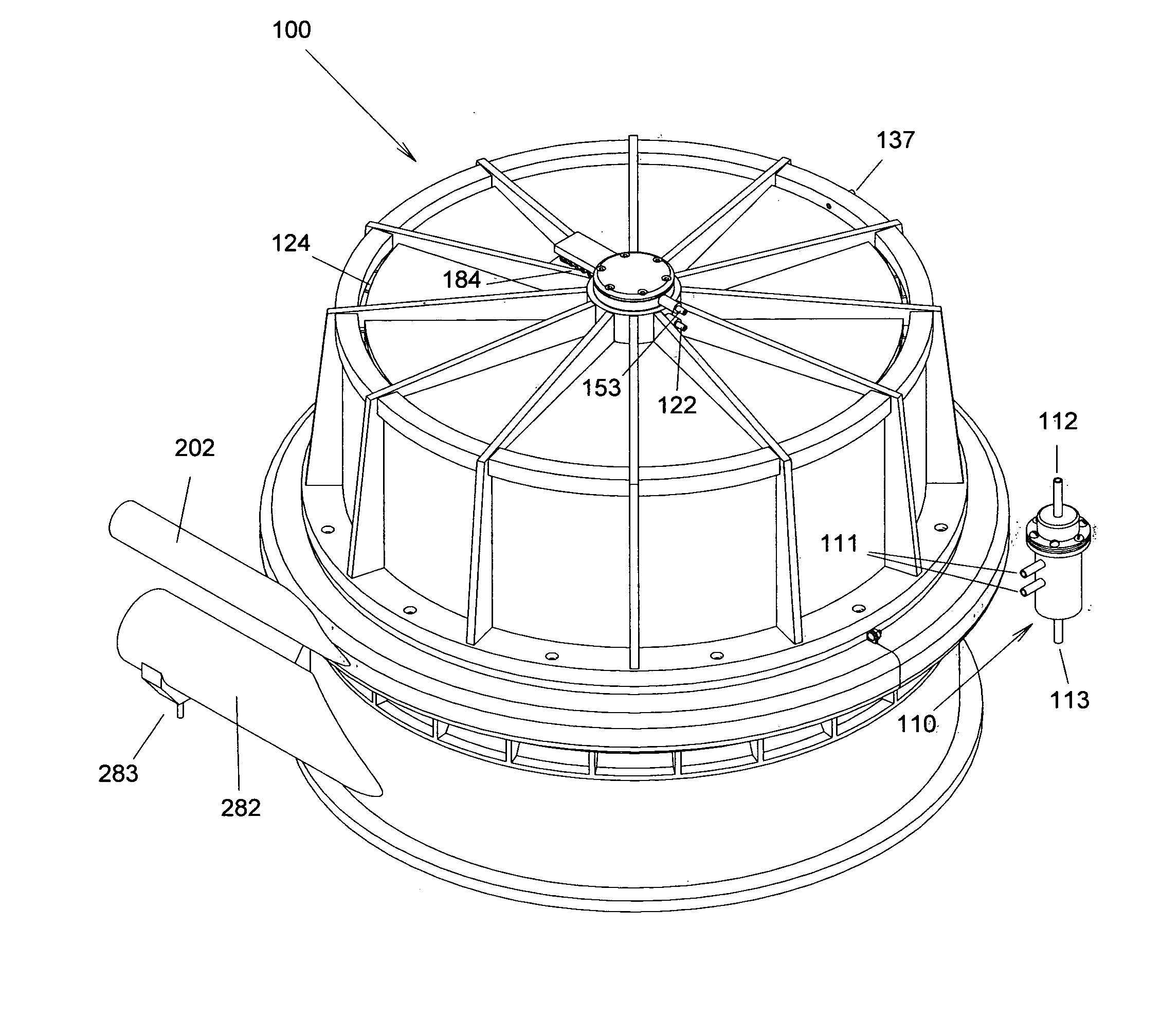
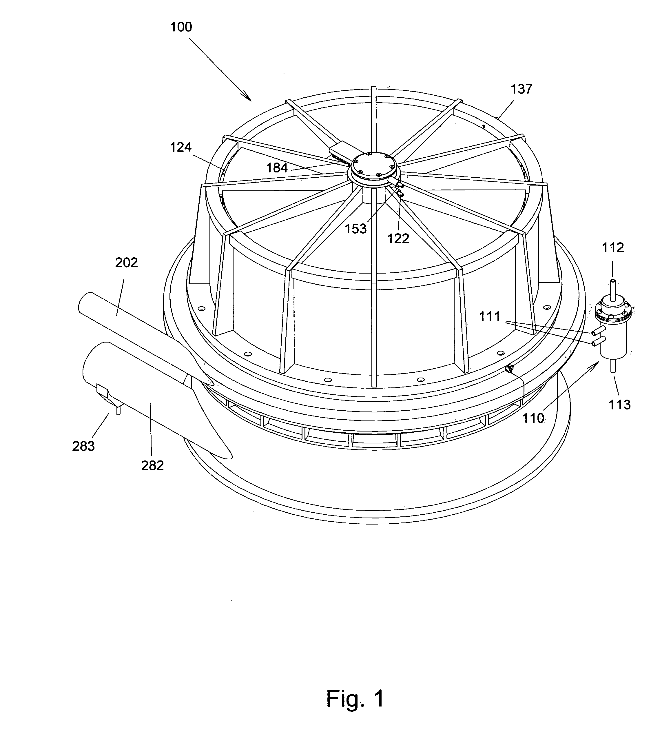
[0075]FIG. 1 is an isometric view of the electrochemical engine, 100. The electrochemical engine is generally cylindrical in form. Fuel enters the engine through fuel inlet ferrule, 153, near the top center of the electrochemical engine. Purged gas and fuel overflow are removed from the engine through a ferrule, 122. Purged gas and liquid fuel are separated in a liquid / gas separator, 110. Purged gas and liquid fuel enter the separator through inlet fittings, 111. Fuel exits through drain fitting, 113, at the base thereof. Purged gas exits through gas return fitting, 112. Purged gas is recirculated through gas return ferrule, 137, on the electrochemical engine. Air enters the engine through a circular array of arc-segment air inlets, 124. Steam exits through exhaust pipe, 202. Recovered fuel byproduct is periodically removed through byproduct-reservoir, clean out pipe, 282. A hose connects a drain fitting on byproduct reservoir drain, 283, to one of the two inlet fittings of the liqu...


PUM

PropertyMeasurementUnit
Angleaaaaaaaaaa
Angleaaaaaaaaaa
Forceaaaaaaaaaa

Abstract

An ion pump that generates a stream of unbalanced aqueous anions that transit from a cathode surface to a region adjacent to an anode surface. The ion pump works in conjunction with an ultrasound generator that produces standing waves having the intensity to dehydrogenate liquid hydrocarbons at the catalytic anode surface. Current density of the ion pump and frequency of the ultrasound transducer are synchronized according to the rate hydrogen permeates through a membrane. An electrochemical engine uses ion pumps and ultrasound generators to convert liquid hydrocarbon fuel to useful work while recovering hydrogen-depleted carbon from the fuel for recycling, including production of renewable fuel. When carbon is recovered, carbon dioxide is not produced. Tensile stress applied to the ion-pump membranes by rotation, high-frequency pressure waves, and radial acceleration of the interstitial hydrogen are applied in a collective manner that facilitates hydrogen permeation through the ion pump membranes.

Description

CROSS-REFERENCE TO RELATED APPLICATIONS[0001]This application claims priority of provisional patent application Ser. No. 60 / 963,500 filed Aug. 6, 2007.FEDERALLY SPONSORED RESEARCH[0002]Not ApplicableSEQUENCE LISTING[0003]Not ApplicableBACKGROUND OF THE INVENTION[0004]1. Field of Invention[0005]This invention is an electrically charged and work activated electrochemical device. The device is disclosed as part of an electrochemical engine that simultaneously produces electricity and mechanical work by dehydrogenating liquid-hydrocarbon fuel.[0006]2. Description of Prior Art[0007]Fuel cells are well known. Fuels cells have provided electricity and drinking water for manned spacecraft for years. The automotive industry has interest in hydrogen-gas, and gasoline-reformer fuel cells for transportation. A hydrogen-economy infrastructure to support widespread use of hydrogen-gas-fueled PEM fuel-cell vehicles is virtually nonexistent. Although the efficiency of hydrogen-fueled fuel cells is ...

Claims


Application Information

Patent Timeline
IPC IPC(8): C25B15/00C25B9/04F02C7/00
CPCH01M14/00
Inventor JOHNSON, ROBERT PAUL
Owner JOHNSON ROBERT PAUL
Why Eureka
Try Eureka