Mobile body mounted with fuel cell

a fuel cell and mobile body technology, applied in the direction of electric devices, process and machine control, final product manufacturing, etc., can solve the problems of fuel cell damage or failure, stop the power generation of fuel cells, and interfere with a further movement of the vehicle, so as to increase the flow rate, and increase the back pressure in the exhaust pipe

Active Publication Date: 2009-02-12
TOYOTA JIDOSHA KK
View PDF9 Cites 17 Cited by
  • Summary
  • Abstract
  • Description
  • Claims
  • Application Information

AI Technical Summary

Benefits of technology

[0018]In this aspect of the invention, during a motion of the moving body on, for example, the water-covered road, the moving body detects the surrounding environment and, upon identification of the potential for any obstructing object to block the outlet or to be flowed into the exhaust pipe through the outlet based on a result of the detection, increases at least one of the flow rate of the fuel gas to the fuel cells by the fuel gas supplier and the flow rate of the oxidizing gas to the fuel cells by the oxidizing gas supplier, regardless of the flow rate of the fuel gas or the oxidizing gas corresponding to the power demand for the fuel cells. During a motion of the moving body equipped with the fuel cells on, for example, the water-covered road, in response to identification of the potential for any obstructing object to block the outlet or to be flowed into the exhaust pipe through the outlet, the emission of the exhaust fluid is increased regardless of the flow rate of the fuel gas or the oxidizing gas corresponding to the power demand for the fuel cells, so as to increase the back pressure in the exhaust pipe. This arrangement enables the moving body to be continuously moved on the water-covered road while preventing the obstructing object from blocking the outlet or from being flowed into the exhaust pipe through the outlet.
[0019]In one preferable embodiment of the moving body according to the above aspect of the invention, the exhaust pipe includes: an anode off gas discharge conduit arranged to flow an anode off gas discharged from anodes of the fuel cells; and a cathode off gas discharge conduit arranged to flow a cathode off gas discharged from cathodes of the fuel cells. The anode off gas discharge conduit joins with the cathode off gas discharge conduit. The anode off gas discharge conduit is equipped with a passage switchover valve arranged to switch over between passage and blockage of the anode off gas discharge conduit. Upon identification of the potential for any obstructing object to block the outlet or to be flowed into the exhaust pipe through the outlet by the decision module, the controller controls an operation of the passage switchover valve to switch over to the blockage of the anode off gas discharge conduit, while increasing the flow rate of the oxidizing gas to the fuel cells by the oxidizing gas supplier, irrespective of the power demand for the fuel cells. In response to identification of the potential for any obstructing object to block the outlet or to be flowed into the exhaust pipe through the outlet, the flow rate of the oxidizing gas to the fuel cells is increased, so as to increase the back pressure in the exhaust pipe. This arrangement effectively prevents the inflow of the obstructing object into the exhaust pipe through the outlet. The blockage of the anode off gas discharge conduit desirably prevents the inflow of the air as the oxidizing gas through the anode off gas discharge cond

Problems solved by technology

During a motion of the conventional vehicle equipped with the fuel cells according to the structure disclosed in Japanese Patent Laid-Open No. 2002-289237 on the water-covered road, however, the outlet may be blocked with water or sediment that is present on the road surface, so as to interfere with the smooth emission of the exhaust gas.
This may stop power generation by the fuel cells and interfere with a further motion of the vehicle.
The water or sediment flowed into the outlet may reach the inside of the fuel cells

Method used


Image

  • Mobile body mounted with fuel cell
  • Mobile body mounted with fuel cell
  • Mobile body mounted with fuel cell

Examples


first embodiment

A. First Embodiment

A1. Configuration of Vehicle

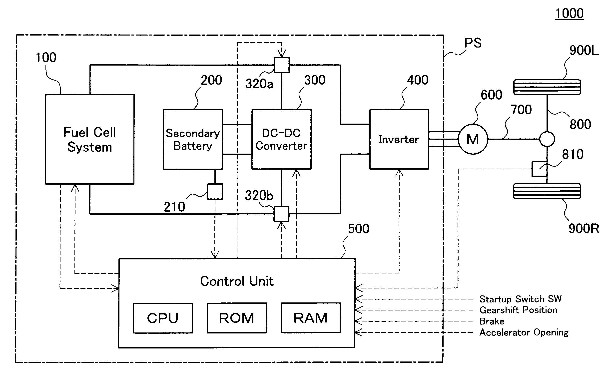
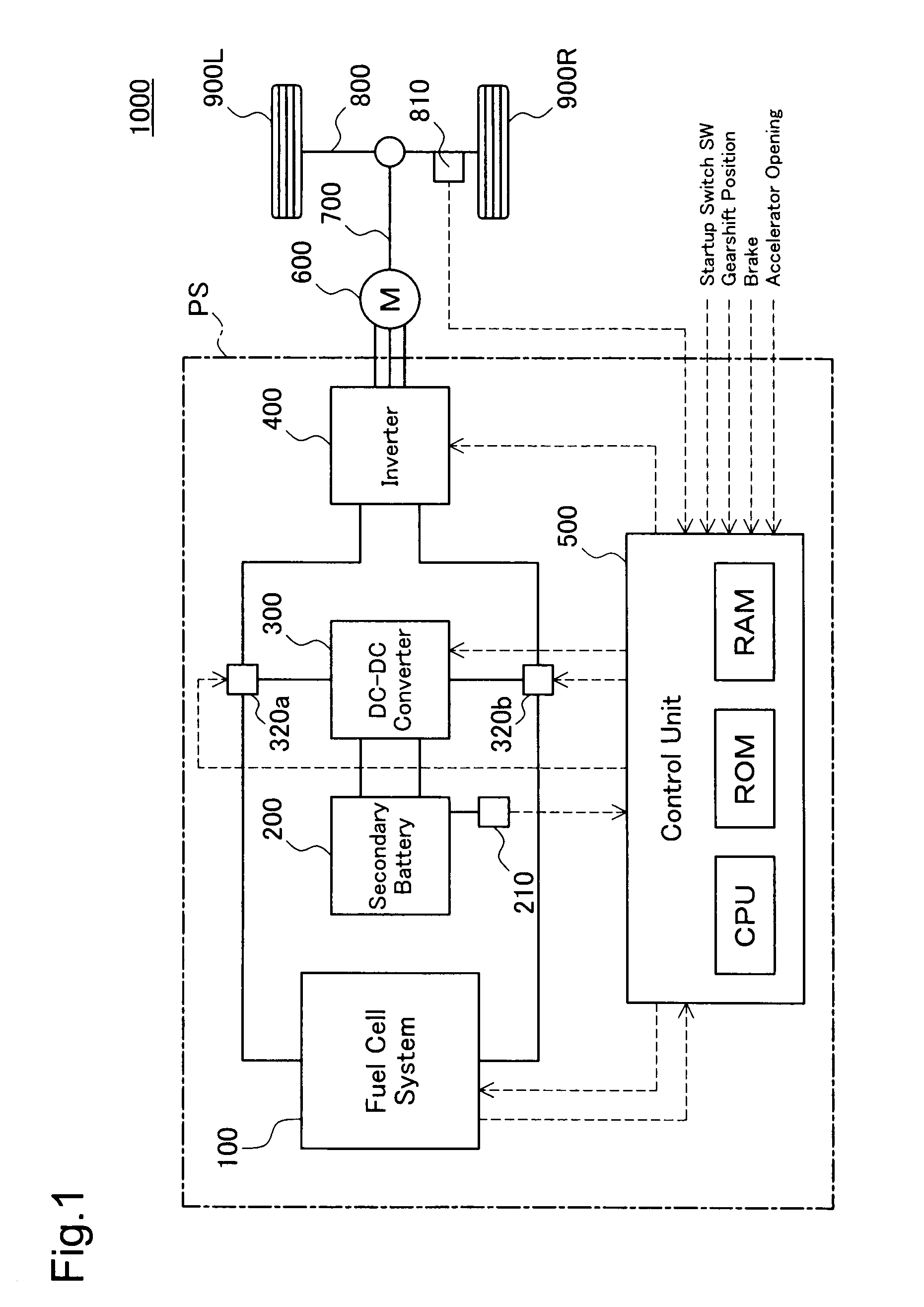
[0039]FIG. 1 schematically illustrates the configuration of a vehicle 1000 in one embodiment of the invention. As illustrated, the vehicle 1000 is an electric vehicle and includes a power system PS and a motor 600.

[0040]The motor 600 is driven with a supply of electric power from the power system PS and accordingly generates and outputs driving power. The output power of the motor600 is transmitted through an output shaft 700 and a driveshaft 800 to wheels 900L and 900R. A vehicle speed sensor 810 is attached to the driveshaft 800. The motor 600 may be any of various types of motors but is a three-shape synchronous motor in this embodiment. The vehicle 1000 is equivalent to the moving body of the invention.

A2. Structure of Power System

[0041]The power system PS has a fuel cell system 100 including a fuel cell stack, a secondary battery 200, a DC-DC converter 300, an inverter 400, and a control unit 500. The secondary battery 200 is equiv...

second embodiment

B. Second Embodiment

[0071]The configuration of a vehicle 1000 in a second embodiment is identical with the configuration of the vehicle 1000 in the first embodiment except partial difference of a fuel cell system 100A mounted on the vehicle 1000. The following describes the structure and the operations of the fuel cell system 100A mounted on the vehicle 1000 of the second embodiment.

B1. Structure of Fuel Cell System

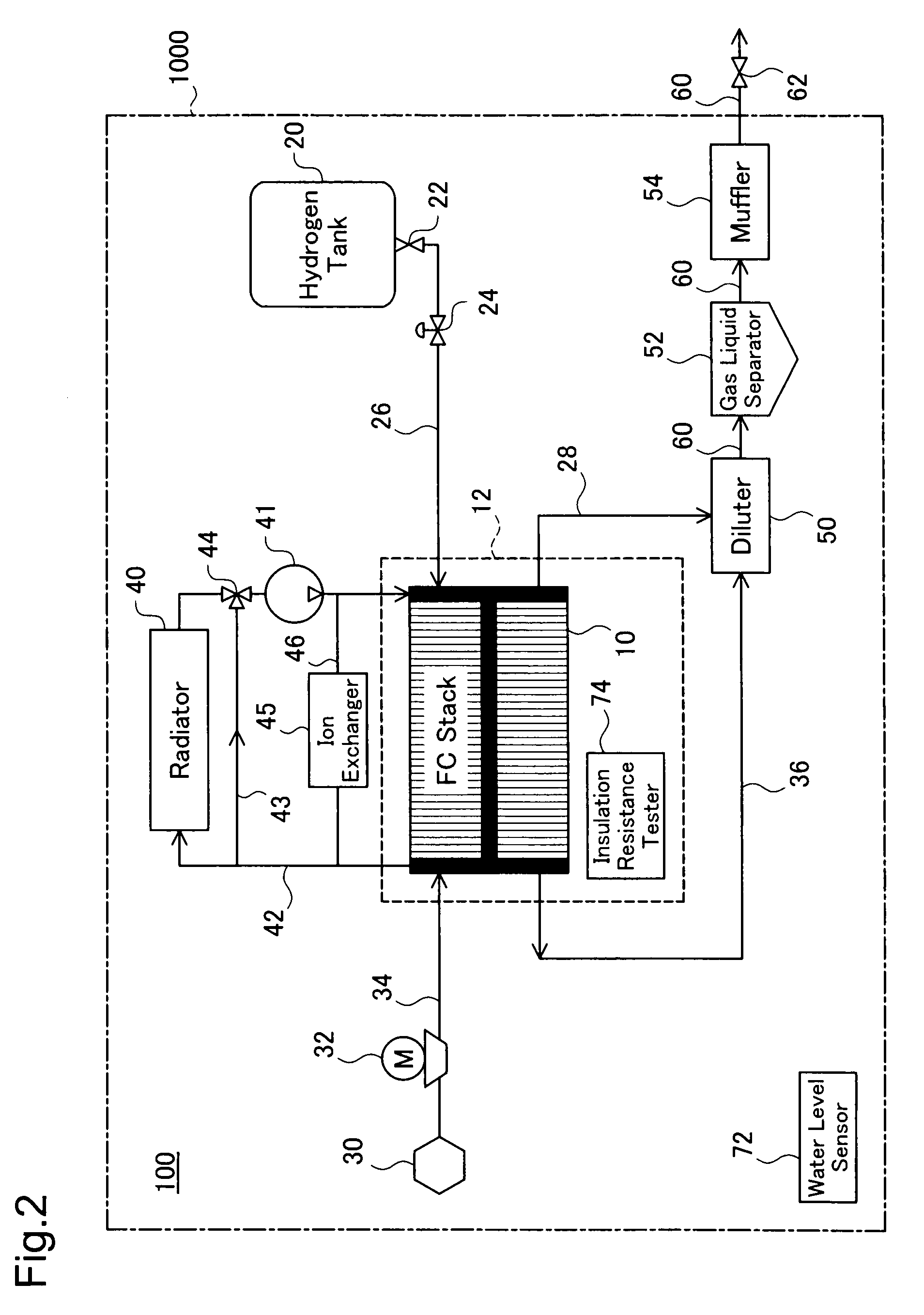
[0072]FIG. 5 schematically shows the structure of the fuel cell system 100A in the second embodiment. As illustrated, the fuel cell system 100A of the second embodiment is similar to the fuel cell system 100 of the first embodiment. The following description thus regards only a different structural part of the fuel cell system 100A of the second embodiment from the fuel cell system 100 of the first embodiment, and explanation of the common structural part is omitted.

[0073]As illustrated, in the fuel cell system 100A of the second embodiment, a valve 29 is provided in the ...

third embodiment

C. Third Embodiment

[0081]The configuration of a vehicle 1000 in a third embodiment is perfectly identical with the configuration of the vehicle 1000 in the first embodiment including the structure of the fuel cell system 100 mounted on the vehicle 1000. The following thus describes only a series of drive control executed in the third embodiment.

[0082]During the motion of the vehicle 1000 on the water-covered road in the FC drive mode, in response to detection of the level of water present on the road surface that is of or over the preset threshold value Hth, the drive control procedures of the first embodiment and the second embodiment explained above stop power generation by the fuel cell stack 10 and switch over the drive mode of the vehicle to the EV drive mode. The drive control procedures of the third embodiment and a fourth embodiment explained below, on the other hand, continuously drives the vehicle 1000 in the FC drive mode even when the level of water present on the water-...


PUM


Abstract

A vehicle 1000 is equipped with a fuel cell system 100 and a secondary battery as power sources. A water level of water present on a water-covered road surface is measured by a water level sensor 72. When the measured water level reaches or exceeds a preset threshold value, drive control of the vehicle 1000 stops power generation by a fuel cell stack 10, closes a discharge valve 62, and enables the vehicle 1000 to be driven with output power of a motor that is actuated with electric power from the secondary battery. This arrangement effectively prevents a damage or failure of the fuel cells mounted on the vehicle moving on the water-covered road.

Description

TECHNICAL FIELD[0001]The present invention relates to a moving body equipped with fuel cells and more specifically to a technique applied to a moving body that is equipped with fuel cells and is driven on water-covered road or its equivalency.BACKGROUND ART[0002]Diverse vehicles equipped with fuel cells have been proposed. In any of these vehicles, electric power generated by the fuel cells is used to drive a motor. The driven motor outputs power to rotate an axle and wheels of the vehicle and accordingly move the vehicle. The vehicle has an exhaust pipe and an outlet arranged to discharge the exhaust gas from the fuel cells to the outside of the vehicle. Like conventional vehicles driven with power of an internal combustion engine, the outlet is typically located below the floor at a rear end of the vehicle body (see, for example, Japanese Patent Laid-Open No. 2002-289237). This arrangement of the outlet enables the exhaust gas discharged from the fuel cells and water produced in t...

Claims


Application Information

Patent Timeline
IPC IPC(8): B60L11/18H01M8/04
CPCB60L3/0046Y02E60/50B60L11/1887B60L11/1892B60L11/1894H01M8/04492H01M8/04656H01M8/04753H01M8/04761H01M8/0494H01M8/04955H01M16/006H01M2250/20Y02T90/32Y02T90/34B60L3/0053B60L58/40B60L58/33B60L58/34B60L58/31Y02P70/50Y02T90/40Y02T10/70Y02E60/10H01M8/00H01M8/04H01M8/10
Inventor JUFUKU, YASUNOBUARISAWA, HIROSHINAGASAWA, JUNJI
Owner TOYOTA JIDOSHA KK
Why Eureka
Try Eureka