Demodulator, Receiver, and Demodulation Method

a receiver and demodulator technology, applied in the field of demodulators, receivers, and demodulation methods, can solve the problems of other modules affecting the demodulation performance and the demodulation performance suffers, and achieve the effect of accurate and fast fourier transform window position recovery

Inactive Publication Date: 2009-02-12
MITSUBISHI ELECTRIC CORP
View PDF3 Cites 26 Cited by
  • Summary
  • Abstract
  • Description
  • Claims
  • Application Information

AI Technical Summary

Benefits of technology

[0007]The present invention demonstrates an effect in which adverse effects of a correlation waveform that has a large proportion of noise components due to the small reception signal power thereof or the like can be suppressed, whereby the clock recovery and the fast Fourier transform window position recovery can accurately be performed.

Problems solved by technology

In an OFDM receiver with a conventional diversity configuration, one of a plurality of demodulation modules is a master module that solely performs clock recovery and fast Fourier transform window position recovery, the results thereof being used by the other modules as well, so if clock recovery or fast Fourier transform window position recovery falters because of, for example, a drop in the received signal level in the master module, the other modules are also affected and demodulation performance suffers greatly.

Method used


Image

  • Demodulator, Receiver, and Demodulation Method
  • Demodulator, Receiver, and Demodulation Method
  • Demodulator, Receiver, and Demodulation Method

Examples


first embodiment

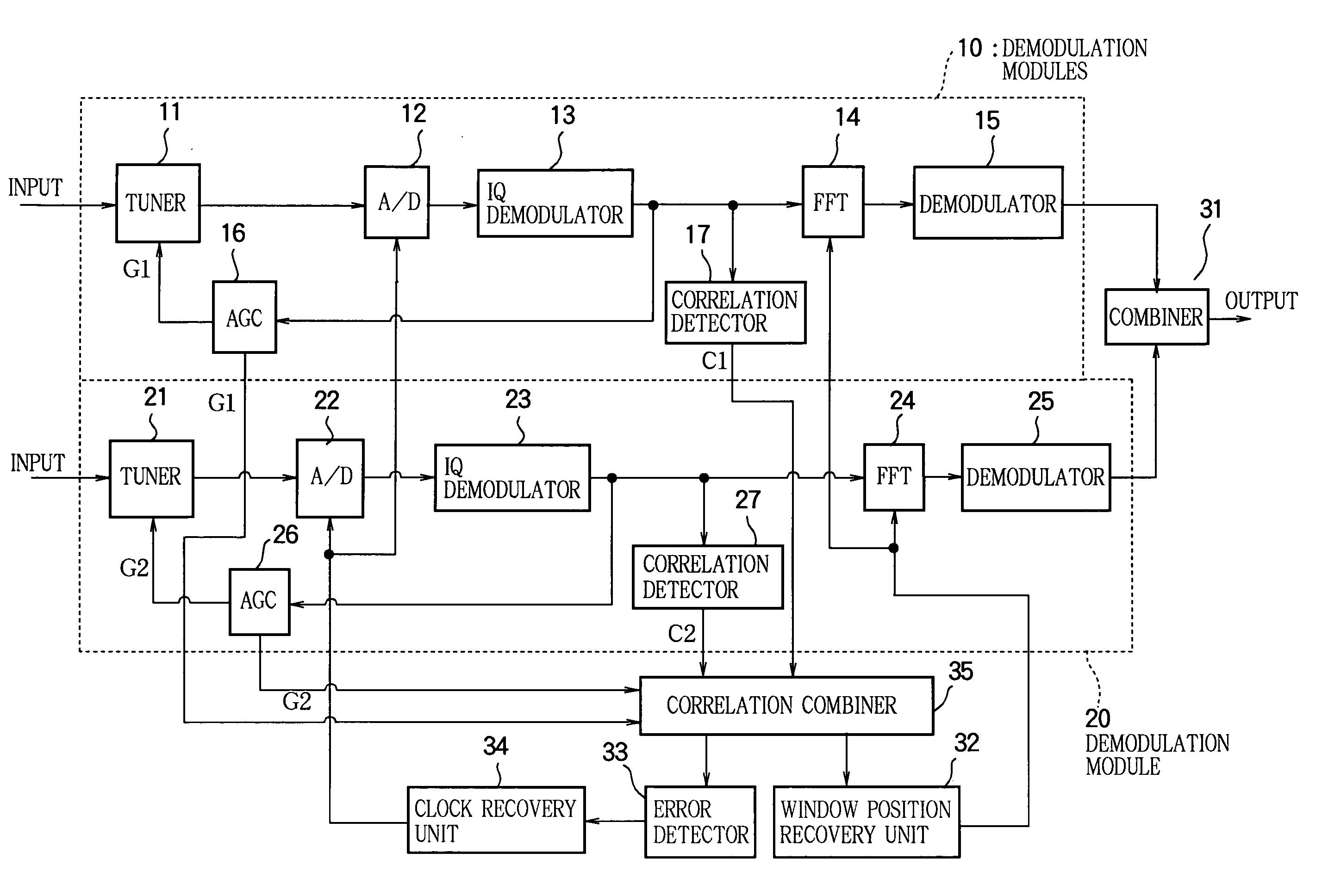
[0019]FIG. 1 is a block diagram showing the structure of a demodulator in a first embodiment of this invention, which is configured for diversity reception with two demodulation modules (a first demodulation module and a second demodulation module) 10, 20. The received signals are input in parallel to the tuners 11, 21 in the demodulation modules 10, 20. The input signals are converted by the tuners 11, 21 to the intermediate frequency band or IF band, then supplied to A / D converters 12, 22. The A / D converters 12, 22 generate output signals in synchronization with a clock signal supplied from a clock recovery unit 34, described below; they convert the outputs of the tuners 11, 21 to digital signals and supply the resulting values to IQ demodulators 13, 23. The input data are converted in the IQ demodulators 13, 23 to complex-valued baseband signals which are supplied to fast Fourier transform (FFT) units 14, 24. Operating according to a window position signal from an FFT window posi...

second embodiment

[0042]FIG. 5 is a block diagram showing the structure of a demodulator in a second embodiment of this invention, which is configured for diversity reception with two demodulation modules 10, 20 as in the first embodiment.

[0043]The structure of the demodulator shown in FIG. 5 is generally similar to the structure shown in FIG. 1, but is equipped with C / N detectors 18, 28 for detecting a C / N value (signal power vs. error signal power ratio) which is the power ratio between the signal actually demodulated and the error of the actually demodulated signal with respect to the originally expected demodulated signal in each module. The C / N values F1, F2 calculated in the C / N detectors 18, 28 are supplied to a correlation combiner 36 together with the correlation waveforms C1, C2 detected by the correlation detectors 17, 27.

[0044]The correlation combiner 36 calculates values proportional to the C / N values F1, F2 supplied from the C / N detectors 18, 28 in each module, multiplies the correlatio...

third embodiment

[0058]FIG. 9 is a block diagram showing the structure of a demodulator in a third embodiment of this invention, which is configured for diversity reception with two demodulation modules 10, 20 as in the first and second embodiments.

[0059]The structure of the demodulator shown in FIG. 9 is generally similar to the structures shown in FIGS. 1 and 5, but is equipped with synchronization acquisition decision units 19, 29, on the assumption that the transmitted OFDM signal includes a known synchronization signal. The synchronization acquisition decision units 19, 29 determine whether acquisition of synchronization with the OFDM signal has succeeded or not by determining whether the known synchronization signal can be correctly demodulated in each module or not, and output resulting synchronization acquisition decision values A1, A2. The correlation waveforms detected by the correlation detectors 17, 27 and the synchronization acquisition decision values output from the synchronization ac...


PUM


Abstract

In an OFDM receiver with a diversity configuration having a plurality of demodulation modules, to perform FFT window position recovery and clock recovery, the gain values calculated by the AGC units (16, 26) provided in the demodulation modules for adjusting the level of the received signal are supplied to a correlation combiner (35); the correlation combiner (35) multiplies the correlation signals supplied from the correlation detectors (17, 27) in the demodulation modules by coefficients calculated from the gain values, then adds the products to generate a combined correlation signal and supplies it to an FFT window position recovery unit (32) and a clock error detector (33). FFT window position recovery and clock recovery can thus be performed properly without depending on any one demodulation module.

Description

FIELD OF THE INVENTION[0001]The present invention relates to a demodulator suitable for an OFDM receiver that receives an OFDM signal in which a symbol interval consists of a guard interval and a valid symbol interval, the trailing part of the valid symbol interval being copied cyclically into the guard interval; more particularly, the invention relates to techniques for clock recovery and fast Fourier transform window position recovery in a diversity receiver. The invention also relates to a receiver equipped with the above demodulator, and to a demodulation method.BACKGROUND ART[0002]In an OFDM receiver with a conventional diversity configuration, one of a plurality of demodulation modules is a master module that solely performs clock recovery and fast Fourier transform window position recovery, the results thereof being used by the other modules as well, so if clock recovery or fast Fourier transform window position recovery falters because of, for example, a drop in the received...

Claims


Application Information

Patent Timeline
Patent Type & Authority Applications(United States)
IPC IPC(8): H03D3/00H04L27/06H04L7/00H04L27/28
CPCH03G3/3036H03G3/3052H04L27/2657H04L27/2676H04L2027/0036H04L2027/0095H04L27/2662
Inventor KADOTA, YUKIHIROTAKEUCHI, MITSURU
Owner MITSUBISHI ELECTRIC CORP
Why Eureka
Try Eureka