Method And Apparatus For Measuring Particle Characteristics through Mass Detection

a technology of mass detection and particle characteristics, applied in the field of methods, can solve problems such as errors in estimated size, difficulty in accurately determining particle size, and light scattering suffering from certain limitations

Active Publication Date: 2009-02-19
MASSACHUSETTS INST OF TECH +1
View PDF4 Cites 20 Cited by
  • Summary
  • Abstract
  • Description
  • Claims
  • Application Information

AI Technical Summary

Problems solved by technology

Light scattering suffers from certain limitations.
For example, when using laser diffraction, determining particle size accurately can be problematic for some applications due to subtleties in the light scattering models.
For a wide class of particles, a priori knowledge of the optical indices of refraction of the particles and the carrying medium is required, and errors in the index values result in errors in estimated size [Keck 2000, Jillavenkatesa 2001].
Other examples include artifacts introduced by irregularly shaped particles that can cause errors when attempting to determine the particle volume and the “equivalent” spherical radius.
Laser diffraction is also known to be problematic when measuring widely polydisperse and multimodal samples, for which measurements may miss entire peaks in the distribution of particle sizes, or indicate spurious peaks in the size distribution [Keck 2000, Driscoll 2001].
The resolution of DLS, i.e., its ability to distinguish among particles closely spaced in size, is fairly low, and this method is not well suited to providing the details of a complex distribution of particle sizes.
The added sample preparation, the need to run several sub-samples, and additional equipment all add time and expense to the overall measurement.
The refined optics needed in these instruments results in high cost, with some instrument prices greater than $50,000.
This can be a burden for applications where the target material is expensive, rare, or difficult to handle.
In addition, light scattering is limited to providing a measure of particle size.
The resolution of this approach is typically limited to sizes above a micron.
Measurements of cell mass and density have been correlated with disease and other physiological states, for example, in the case of malaria [Kramer 1982], but the measurement techniques for these quantities remain laborious.

Method used


Image

  • Method And Apparatus For Measuring Particle Characteristics through Mass Detection
  • Method And Apparatus For Measuring Particle Characteristics through Mass Detection
  • Method And Apparatus For Measuring Particle Characteristics through Mass Detection

Examples


Embodiment Construction

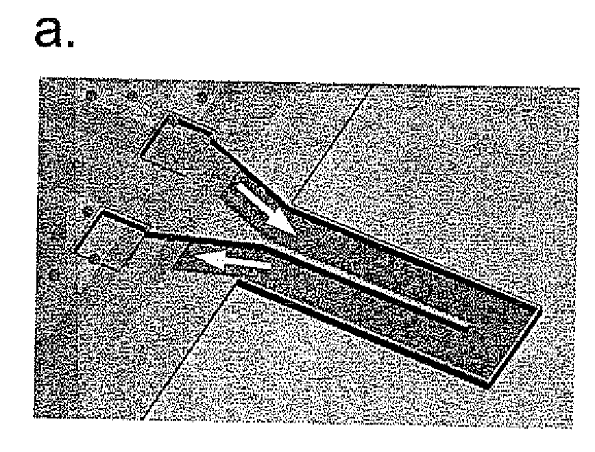
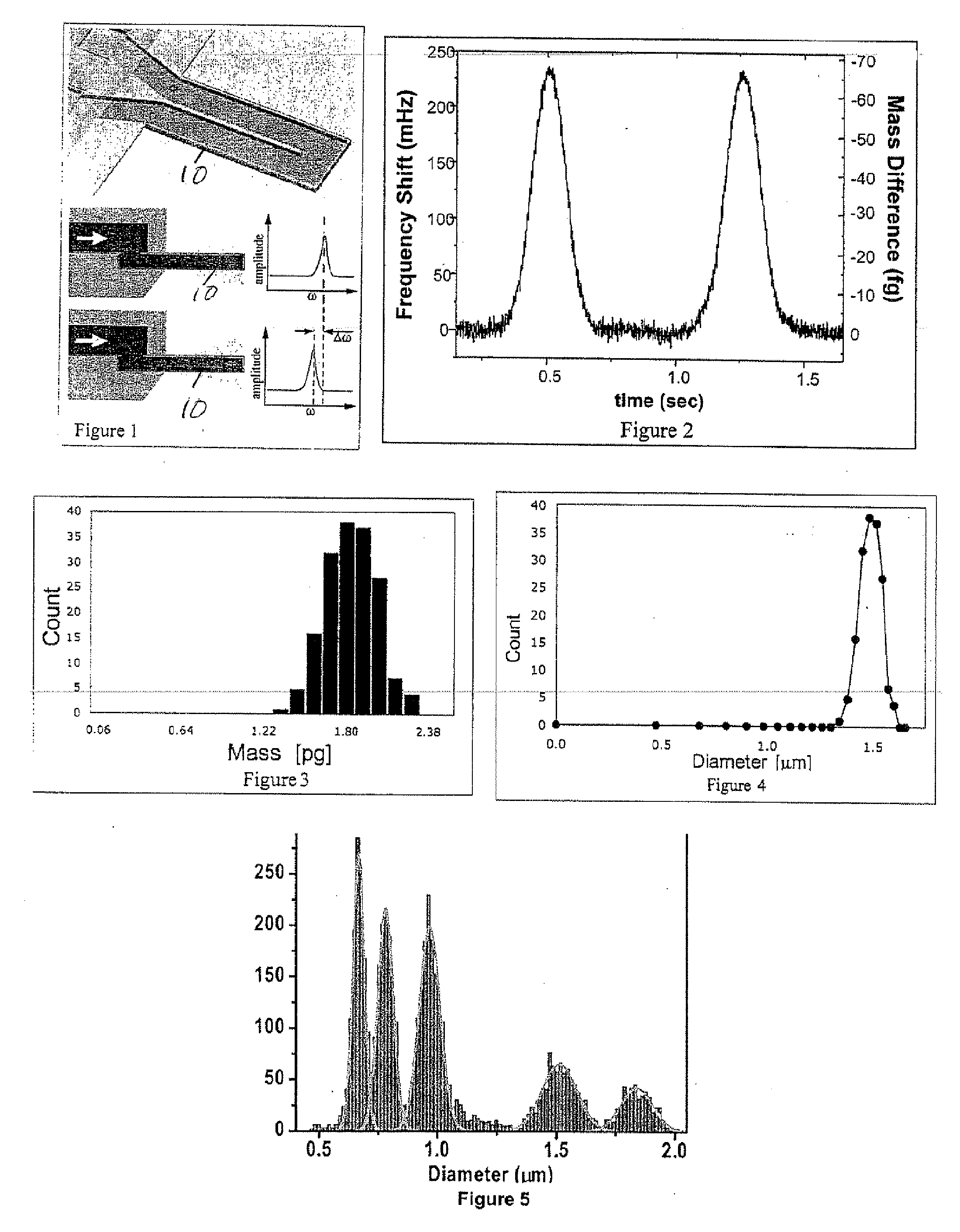
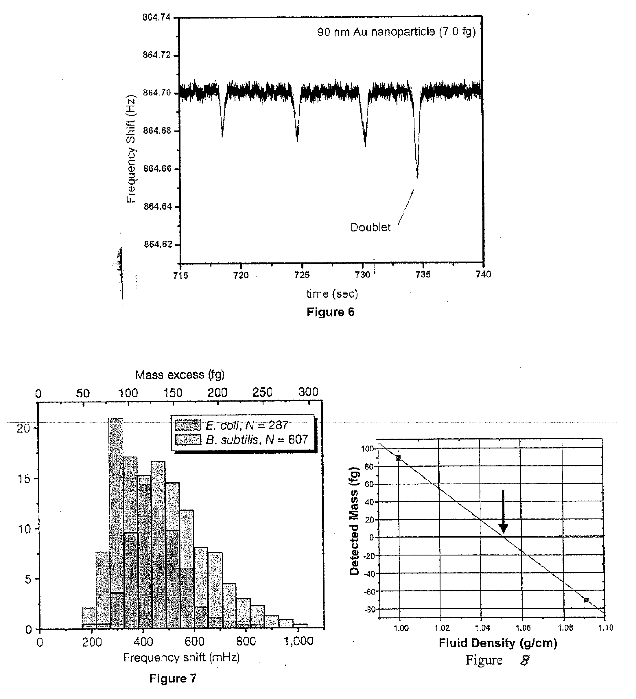
[0025]Here we propose a new method for measuring the mass, size, and density of particles whose sizes range from the nanometer scale to many microns. The method employs a recently-introduced mass sensor known as the suspended microchannel resonator (SMR) [Burg and Manalis 2003; Burg 2007]. The SMR uses a fluidic microchannel embedded in a resonant structure, one type being in the form of a cantilever 10 (FIG. 1). The top diagram in FIG. 1 is cutaway to show the microchannel interior, but in fact the channel is fully enclosed. Target particles are carried through the sensor in a fluid, and their contribution to the total mass within the sensor causes the resonance frequency of the sensor to change in relation to the particle mass. By using microfabrication techniques, SMR sensors can be fabricated with mass resolution of less than 1 femtogram (10−15 g). This resolution is sufficient to detect and measure the mass of individual particles in the range of several nanometers up to many m...


PUM

PropertyMeasurementUnit
sizesaaaaaaaaaa
sizesaaaaaaaaaa
mass resolutionaaaaaaaaaa

Abstract

Method for measuring a target particle property. A suspended microchannel resonator is calibrated to determine the relationship between a detected mass and a resonance frequency shift of the resonator. The target particle is suspended in a fluid and introduced into the resonator, and the resonator frequency shift due to the particle is measured. Target particle mass is calculated from the resonator frequency shift, the target particle density, and the fluid density. A target particle property such as size or volume is determined from the calculated target particle mass.

Description

[0001]This application claims priority to provisional application Ser. No. 60 / 850,776 filed Oct. 11, 2006, the contents of which are incorporated herein by reference.BACKGROUND OF THE INVENTION[0002]This invention relates to method and apparatus for measuring a property such as mass, size or density of target particles, and more particularly to such a method using a suspended microchannel resonator.[0003]Precision measurements of nanometer- and micrometer-scale particles have wide application in pharmaceuticals / drug delivery, paints and coatings, foods, and other major industries and fields of research. This need is growing due to the expanding use of particulate engineering across these industries, to emerging nano- and micro-particle manufacturing techniques, and to recent regulations governing quality control in the pharmaceutical industry.[0004]The most widely used particle-sizing technology is light scattering [Jillavenkatesa, 2001]. The names in brackets refer to the attached ...

Claims


Application Information

Patent Timeline
Patent Type & Authority Applications(United States)
IPC IPC(8): G01N29/22
CPCG01N2015/1043G01N2015/1087G01N5/00G01N9/002G01N15/0255G01N15/1012G01N2015/003G01N15/00G01N15/10
Inventor BABCOCK, KENNETHBURG, THOMASGODIN, MICHELMANALIS, SCOTT
Owner MASSACHUSETTS INST OF TECH
Why Eureka
Try Eureka