Vacuum processor

a technology of vacuum processor and rotary blade, which is applied in the direction of vacuum evaporation coating, electrolysis components, coatings, etc., can solve the problems of difficult capture of adhesive materials in pipes, adverse effect on yield of semiconductor elements, and difficulty in passing through the vanes of the rotary blade to the pump, so as to reduce the degradation of yield of members, restrain the exposure of the front end of the peripheral part, and restrain the degradation of yield

Inactive Publication Date: 2009-02-19
RENESAS ELECTRONICS CORP
View PDF9 Cites 3 Cited by
  • Summary
  • Abstract
  • Description
  • Claims
  • Application Information

AI Technical Summary

Benefits of technology

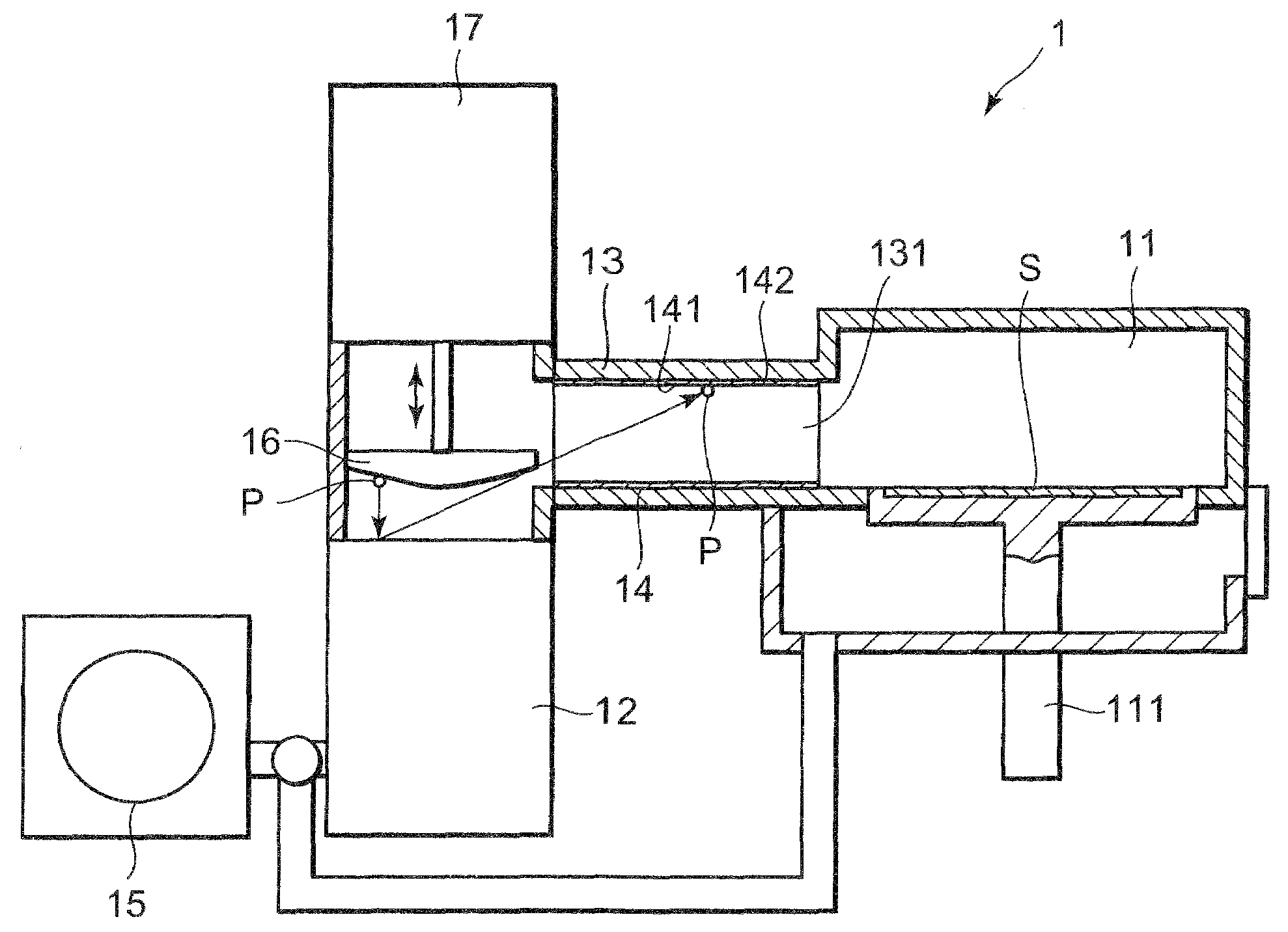
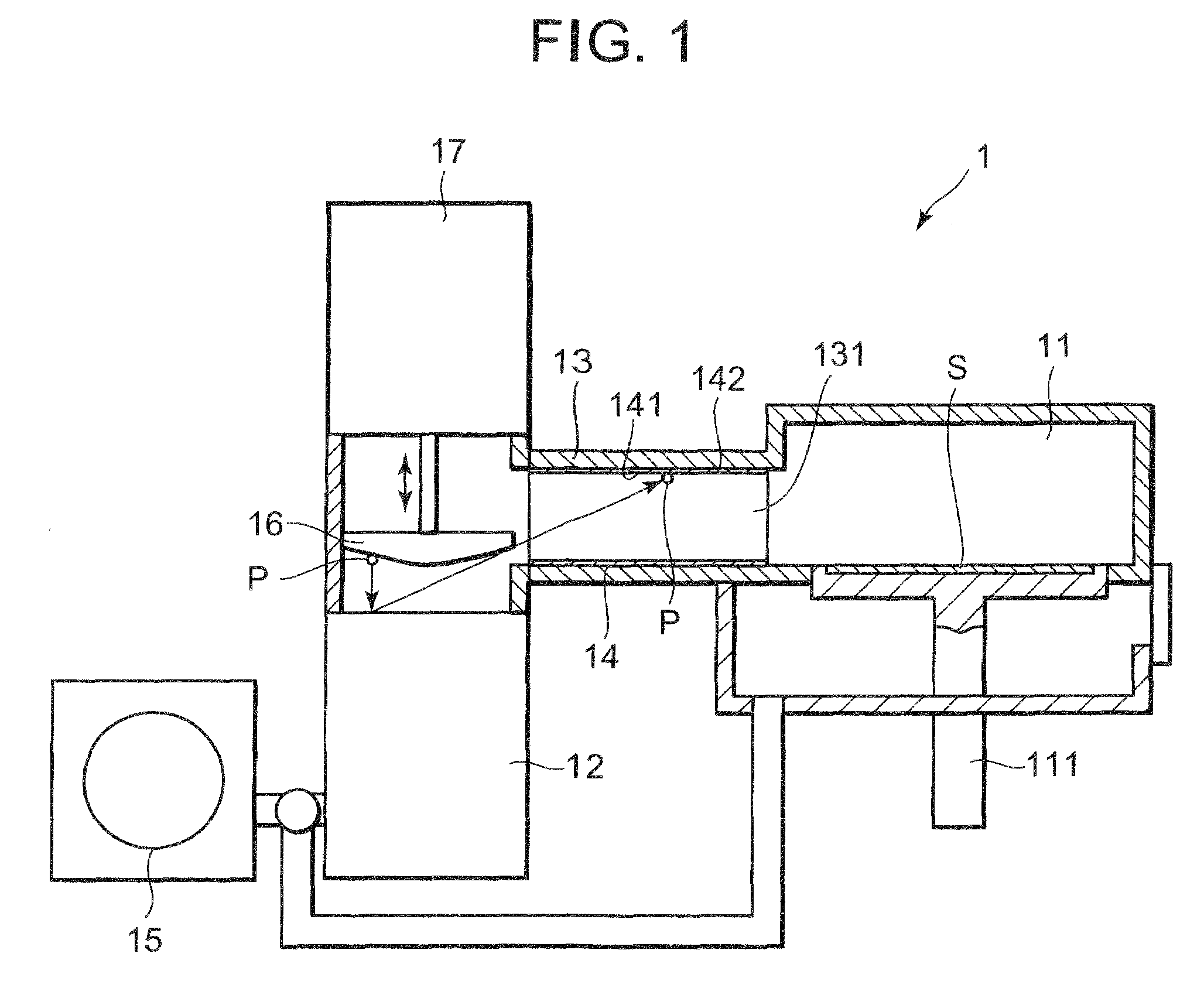
[0015]By providing a fibrous substance facing the gas passage within the connection part in the capturing part in this way, bouncing particles can be restrained, like use of a conventional adhesive material, and particles bounced by the pump rotary blades can be prevented from invading into a chamber. This can restrain degradation of yield of members manufactured with a vacuum processor.
[0016]In the present invention, the fibrous substance has the surface of woven cloth or unwoven cloth facing a passage, the peripheral part of the woven cloth or the unwoven cloth is folded to a back side and the front end of the peripheral part is interfolded to the back side. Specifically, in the present invention, the peripheral part front end of the woven cloth or the unwoven cloth constituting the fibrous substance is interfolded to a back side, which restrains exposure of the peripheral part front end. Accordingly, dust generated from the peripheral part front end of the woven cloth or the unwoven cloth constituting the fibrous substance can be restrained from invading into the passage and further the chamber. This enables more restraint of degradation of yield of a member manufactured with the vacuum processor.
[0017]In order to suppress generation of particles, it is thought that the peripheral part of woven cloth or unwoven cloth of a fibrous substance is solidified by being impregnated with resin having relatively high corrosion resistance such as polyimide resin. However, in this case, the resin-impregnated portion does not contribute on capturing of particles and further the penetrating width becomes difficult to control, thus reducing an area contributing to capturing of particles. On the contrary, in the case of the present invention, the peripheral part front end of woven cloth or unwoven cloth constituting the fibrous substance is interfolded to the back side, which can restrain reduction in the area contributing to capturing of particles.

Problems solved by technology

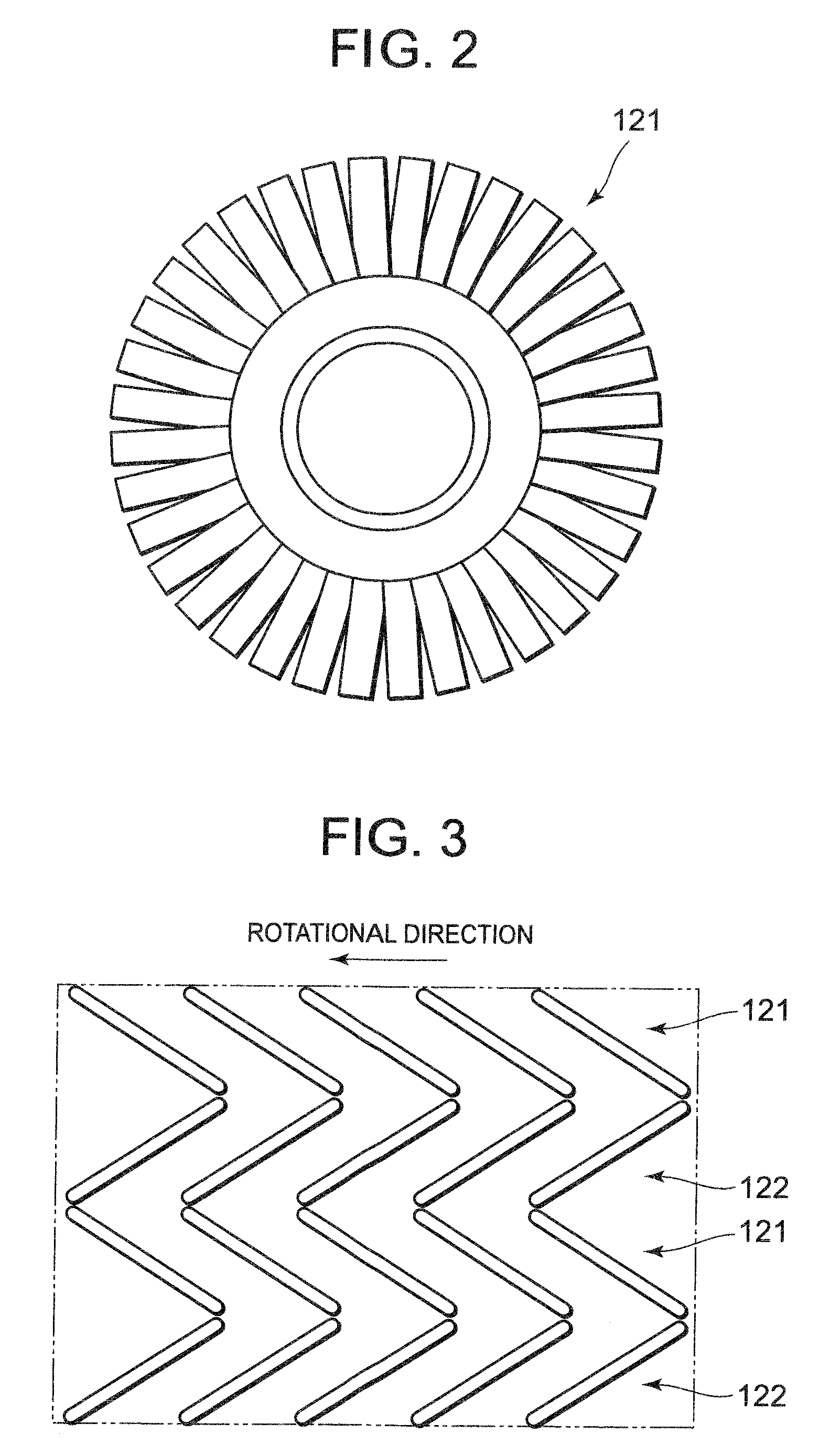
The pump rotary blades rotate at a high speed, for example, approximately 36,000 revolutions / sec and therefore it is very difficult for the particles dropped onto the pump to pass through between vanes of the rotary blades.
Accordingly, it is thought that adhesive material in the pipe is difficult to be captured.
Hence, it is thought that the particles will reach semiconductor substrate or the like in the vacuum container, thereby having an adverse effect upon yield of semiconductor elements.
However, it has now been discovered that vacuum processors disclosed by Japanese Patent Application Laid-Open Nos. 3-118815 and 2007-180467 cannot restrain degradation of yield in spite of provision of an adhesive material or a flocculent body.
However, dust generates from a flocculent body and therefore yield of semiconductor elements cannot be restrained from being degraded.
It is thought that dust is apt to generate from the portion to be cut and therefore yield of semiconductor elements cannot be restrained from being degraded.
However, in this case, the resin-impregnated portion does not contribute on capturing of particles and further the penetrating width becomes difficult to control, thus reducing an area contributing to capturing of particles.

Method used


Image

  • Vacuum processor
  • Vacuum processor
  • Vacuum processor

Examples


first embodiment

[0054]Referring to FIGS. 9 to 11, description will be made on a first embodiment of the present invention below. In the present embodiment, as illustrated in FIG. 9, a fibrous substance 241 includes woven cloth 243 having a surface facing the passage 131 and unwoven cloth 242 having a surface on the passage 131 side covered with the woven cloth 243. The peripheral part of the woven cloth 243 is folded to the back side of the unwoven cloth 242 (also corresponding to the back side of woven cloth 243) and a peripheral part front end 243A of the woven cloth 243 is interfolded to the back side of the unwoven cloth 242. Other respects are the same as for the basic configuration described above.

[0055]The unwoven cloth may be formed by a needle punch method. Otherwise, the span bond method, thermal bond method or chemical bond method may be used. Of the above-methods, preferably, the needle punch method is used. Some materials of the unwoven cloth 242 are difficult to cause fusion between f...

second embodiment

[0069]Referring to FIG. 12, a second embodiment of the present invention will now be described. In the first embodiment, the fibrous substance 241 has the unwoven cloth 242 and the woven cloth 243. On the other hand, in the present embodiment, a fibrous substance 441 has a first woven cloth 443 having a surface facing a passage 131 and a second woven cloth 442 having a surface on the passage 131 side covered with the first woven cloth 443. Other respects are the same as for the embodiment described above.

[0070]The first woven cloth 443 covers the whole surface of one face of the second woven cloth 442 on the passage 131 side, and a peripheral part thereof is folded to the other face of a second woven cloth 442 (back face of the second woven cloth 442, also corresponding to back side of the first woven cloth 443) and the peripheral part front end of the first woven cloth 443 is interfolded to the other face side of the second woven cloth 442. The way of folding the peripheral part of...


PUM

PropertyMeasurementUnit
aperture diameteraaaaaaaaaa
lengthaaaaaaaaaa

Abstract

A vacuum processor includes: a chamber; a pump which keeps the inside of the chamber in a vacuum state by; a connection part which connects the chamber with the pump and is formed with a gas passage therein. An inner wall of the connection part is provided with a capturing part capturing particles in the passage. The capturing part has a fibrous substance facing the passage and disposed along the passage. The fibrous substance is provided to capture particles. A peripheral part of the woven cloth of the fibrous substance is folded to a back side of the unwoven cloth and the front end of the peripheral part of the woven cloth is interfolded to the back side of the unwoven cloth.

Description

[0001]This application is based on Japanese patent application No. 2007-210845, the content of which is incorporated hereinto by reference.BACKGROUND OF THE INVENTION[0002]1. Field of the Invention[0003]The present invention relates to a vacuum processor.[0004]2. Description of the Related Art[0005]Conventionally, a vacuum processor, such as a CVD apparatus, a sputtering apparatus or a dry etching apparatus, has been used to manufacture semiconductor elements and electronic parts. In such apparatuses, an object to be processed, such as a semiconductor substrate is placed in a chamber and the internal chamber is kept a vacuum state for treatment, such as thin-film formation.[0006]If particles adhere to the semiconductor substrate, yield decreases. Accordingly, various approaches have been made.[0007]Japanese Patent Application Laid-Open Nos. 60-227421, 2001-338906 and 7-312363 have disclosed a technology of providing an adhesive coating layer over the whole chamber, respectively.[000...

Claims


Application Information

Patent Timeline
Patent Type & Authority Applications(United States)
IPC IPC(8): H01L21/306C23C14/56
CPCC23C16/4412
Inventor SATO, FUMIHIDE
Owner RENESAS ELECTRONICS CORP
Why Eureka
Try Eureka