Microchip and analysis method using the microchip

a microchip and analysis method technology, applied in the field of microchips, can solve the problems of contaminating the analysis sample, requiring a long time for drying, and requiring complex equipment for freeze-drying at reduced pressure, so as to reduce the amount of moisture, reduce the time required for drying the adhered frost, and improve the reproducibility

Inactive Publication Date: 2009-02-19
NEC CORP
View PDF4 Cites 15 Cited by
  • Summary
  • Abstract
  • Description
  • Claims
  • Application Information

AI Technical Summary

Benefits of technology

[0060]By using the above-described microchip to carry out the above-described sample analysis method, the cover-detaching step becomes more complex, but the drying step can be carried out with good reproducibility. This effect can be obtained because decreasing the amount of moisture in the gas atmosphere surrounding the substrate when removing the cover from the cooled substrate reduces the amount of frost that adheres to the substrate and can thus prevent the destruction of the separated state of the substance that is the object of analysis when frost on the substrate surface melts during heating of the substrate and flows into the channel. In addition, the time required for drying the adhered frost is shortened. As a result, after separation and freezing of the analysis sample, the cover can be removed from ...

Problems solved by technology

As in Non-Patent Document 2, using a channel that is left open gives rise to the problems that during separation by electrophoresis, substances outside the chip may enter the channel and thus contaminate the analysis sample or the analysis sample inside the channel may spill out of the channel.
Freeze-drying for dryi...

Method used


Image

  • Microchip and analysis method using the microchip
  • Microchip and analysis method using the microchip
  • Microchip and analysis method using the microchip

Examples


first embodiment

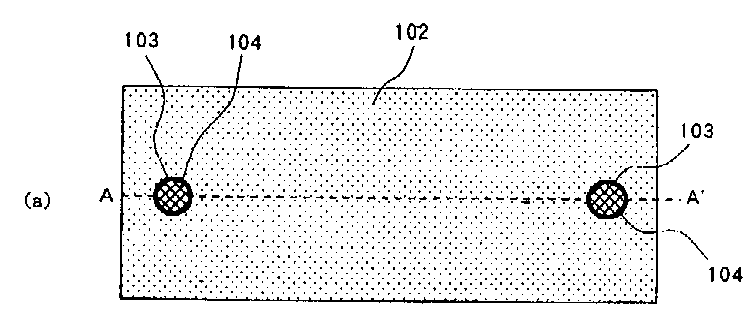
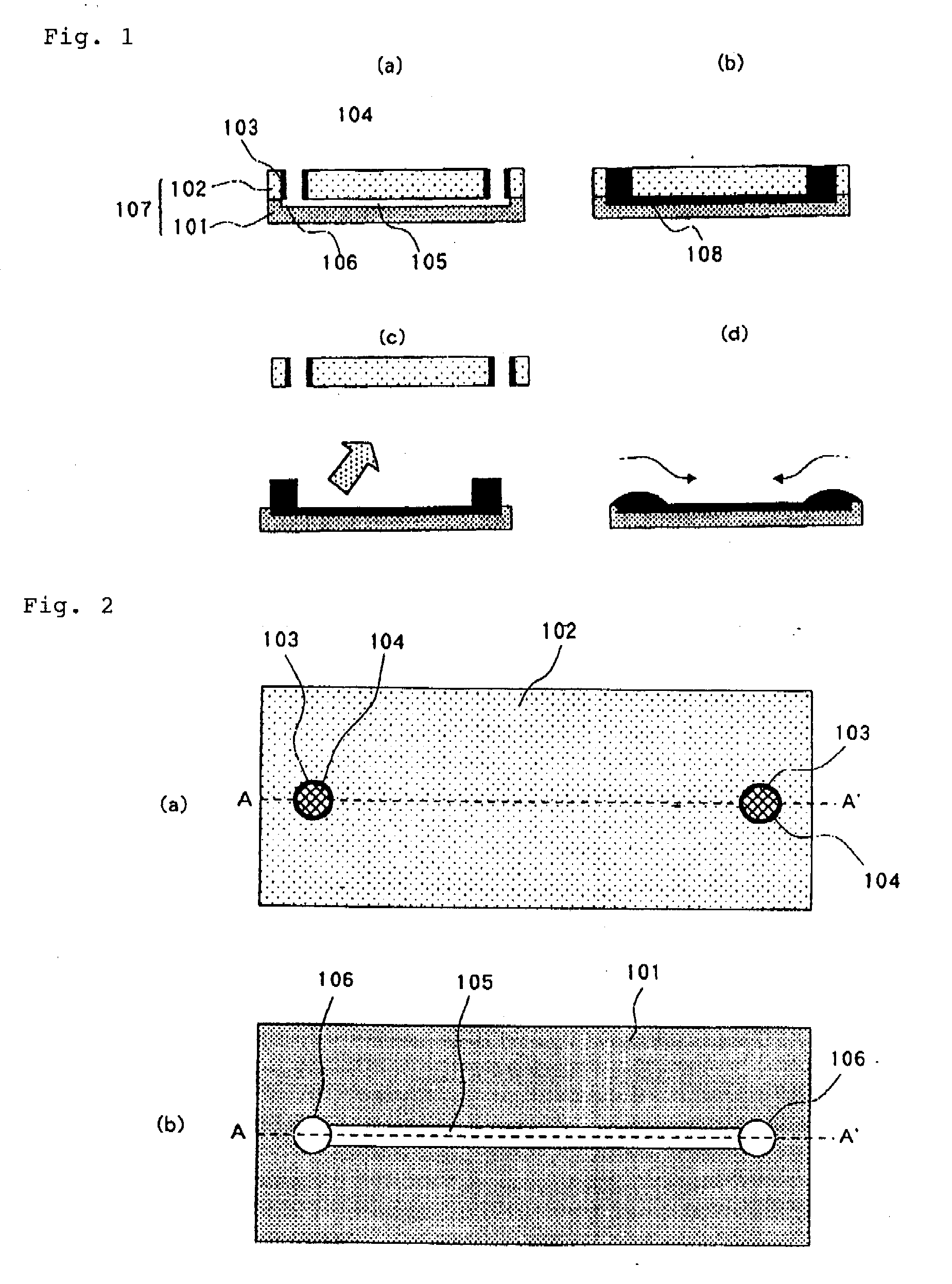
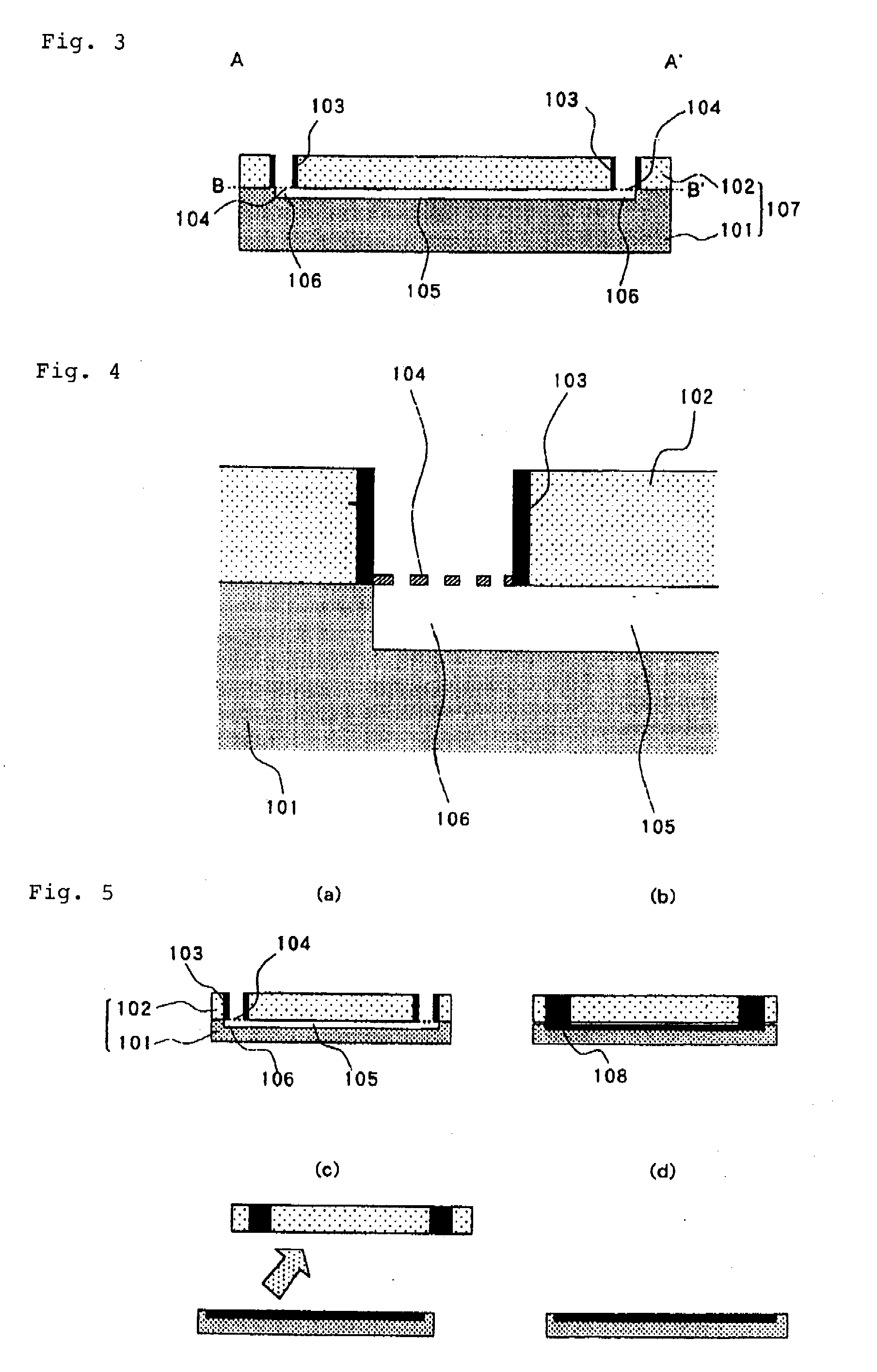
[0082]FIG. 2(a) is a top view showing the constituent parts of the microchip of the present embodiment, and FIG. 2(b) is a top view showing the constituent parts of the microchip of the present embodiment at section B-B′ of FIG. 3. FIG. 3 is a cross-sectional view showing the section at A-A′ of the microchip of the present embodiment shown in FIG. 2(a). FIG. 4 is a cross-sectional view showing an enlargement of a section in the vicinity of a cover reservoir of the microchip of the present embodiment. FIG. 5 is a cross-sectional view showing in stages the analysis operations that use the microchip of the present embodiment.

[0083]In the channel configuration of the present embodiment, substrate 101 is provided on its upper surface with channel 105 that is used in the separation of the substance that is the object of analysis. Substrate reservoirs 106 are formed at both ends of channel 105.

[0084]Cover 102 that seals channel 105 of substrate 101 is provided with through-holes at positio...

second embodiment

[0099]FIG. 6 is a cross-sectional view showing an enlarged cross section in the vicinity of cover reservoir 103 of the microchip according to the present embodiment, The microchip according to the present embodiment is of the same microchip configuration as the first embodiment, differing only regarding the configuration of partitions 104. Partitions 104 of the present embodiment are of a convex construction that protrude toward the inside diameter of cover reservoir 103.

[0100]As in the first embodiment, after the substance that is the object of analysis has been separated in channel 105, substrate 101 is cooled to freeze the analysis sample and reservoir liquid. Cover 102 is removed from substrate 101 with the analysis sample remaining frozen. At this time, partitions 104 cause the frozen reservoir liquid to break along partitions 104, and the frozen reservoir liquid can thus be split between the side of cover reservoirs 103 of cover 102 and the side of substrate reservoirs 106. Th...

third embodiment

[0103]FIG. 7 is a cross-sectional view of the microchip according to the present embodiment. FIG. 8 is a top view showing the constituent parts of the microchip of the present embodiment. FIG. 7 shows an enlargement of a cross section in the vicinity of a cover reservoir between A-A′ in FIG. 8(a), FIG. 8(a) shows the state in which substrate 101 and cover 102 are combined, and FIG. 8(b) shows the cutting plane that joins B-B′ in FIG. 7 (top view of cover 102).

[0104]The microchip according to the present embodiment is of the same microchip configuration as the first embodiment and second embodiment but includes cover reservoirs 103 and substrate reservoirs 106 at the two ends of channel 105 as well as at positions inward from the two ends, resulting in a total of four of each: two cover reservoirs 103 and substrate reservoirs 106 at the two ends and two cover reservoirs 103 and substrate reservoirs 106 at positions inward from the two ends.

[0105]Cover reservoirs 103b provided at the ...


PUM

PropertyMeasurementUnit
Diameteraaaaaaaaaa
Widthaaaaaaaaaa
Areaaaaaaaaaaa

Abstract

With the object of realizing a microchip that allows drying and fixing of a substance that is the object of analysis in a shorter time while maintaining the separation capabilities of a separation operation, a microchip used to implement a separation operation of an analysis sample without contamination or spillage is composed of a substrate and a cover, the substrate being provided with a trench-shaped channel in its upper surface and substrate reservoirs that are linked with this channel, and the cover hermetically sealing the upper surface of the channel, attachable to or detachable from the substrate, and provided with through-holes formed at positions corresponding to the substrate reservoirs, cover reservoirs that are formed on the inner sides of the through-holes for holding liquid that is introduced when the cover is in the state of hermetically sealing the upper surface of the channel, and partitions that are formed on the bottom surfaces of the cover reservoirs. The areas of the openings of the partitions are smaller than the areas of the openings of the cover reservoirs that are over the partitions.

Description

TECHNICAL FIELD[0001]The present invention relates to a microchip for use in biochemical analysis and to an analyzing method of using the microchip to analyze samples that contain biological / chemical substances.[0002]The microchip for use in bio / chemical analyses and the sample analysis method that uses the microchip according to the present invention can be used for improving the reproducibility of further biochemical analyses that use analysis samples that have been separated on the microchip, such as sample analysis processes for mass spectrometry or bio-assay analyses.BACKGROUND ART[0003]Regarding samples to be analyzed that contain biological substances and chemical substances that are to be subjected to analysis, various types of electrophoresis, chromatography, bio-assays and chemical assays are used when analyzing and identifying the substances that are the objects of analysis. In these analysis methods, the separation and measurement of bio-reactivity and chemical reactivit...

Claims


Application Information

Patent Timeline
IPC IPC(8): G01N27/26B01J19/00
CPCB01L3/502707G01N27/44791B01L7/50B01L2200/027B01L2200/0678B01L2300/046B01L2300/047B01L2300/0645B01L2300/0681B01L2300/0816B01L2300/161B01L2400/0406B01L2400/0421B01L2400/086B01L3/502746
Inventor FUJITA, MACHIKOKAWAURA, HISAOHATTORI, WATARU
Owner NEC CORP
Why Eureka
Try Eureka