
High Voltage SEPIC Converter

a high-voltage sepic converter and converter technology, applied in the direction of electric variable regulation, process and machine control, instruments, etc., can solve the problems of inability to step up and step down regulation, damage to the device, and inability to survive high input voltag

Inactive Publication Date: 2009-02-19
ADVANCED ANALOGIC TECHNOLOGIES INCORPORATED
View PDF5 Cites 31 Cited by
  • Summary
  • Abstract
  • Description
  • Claims
  • Application Information

AI Technical Summary

Benefits of technology

[0009]To this basic SEFIC topology just described, a first embodiment of the present invention adds circuitry for over-voltage protection. Specifically, this embodiment uses over-voltage protection MOSFET to connect the input supply to the PWM control circuit and the node Vw. The over-voltage protection MOSFET is driven by the output of a comparator. The comparator is connected to monitor the difference between a predetermined reference voltage Vref and the voltage of the input supply. If the voltage of the input supply exceeds the predetermined value Vref the comparator output causes the over-voltage protection MOSFET to disconnect the node Vw and the PWM control circuit from the input supply. In this way, a SEPIC converter is provided that can survive input voltages that would otherwise damage the power MOSFET or PWM control circuit.
[0010]A second embodiment of the present invention provides a high-voltage SEPIC converter. For this embodiment (once again, based on the topology described above) a linear regulator (typically, an LDO) is used to supply current from the input supply to the PWM control circuit. In this way, the voltage applied to the PWM control circuit never exceeds the regulated output of the linear regulator and the SEPIC converter can survive input voltages that would otherwise damage the PWM control circuit.
[0014]The current through the P-channel MOSFET is monitored using a current mirroring technique. This produces an over-current signal that is connected as an input to the AND gate (in this implementation the AND gate has three inputs). If current flowing through the P-channel MOSFET exceeds a predetermined value, the over-current signal causes the AND gate to disable the output of the PWM control circuit. In turn, this causes the power MOSFET to turn OFF and protects the SEPIC converter from over-current damage. The use of a P-channel MOSFET to monitor the current to the high-side inductor also means that, by biasing that MOSFET to be OFF, the SEPIC converter may be disconnected from the input supply.

Problems solved by technology

Most DC to DC switching voltage regulators such as the Buck converter and boost converter are capable of only regulating a voltage above or below a given input but not capable of both step up and step down regulation.
Instead of limiting the maximum input voltage, converter 1 continues to operate at any input voltage until the drain voltage on MOSFET 3 exceeds safe limits and damages the device.
In addition to this inability to survive high input voltages, PWM controller 2 contains low-voltage control circuitry which cannot operate when powered directly from a high voltage input.
The circuit as shown also suffers from the lack of a true load disconnect.
Current sensing is also problematic since there is no convenient means to detect the input current in inductor 5.

Method used


Image

  • High Voltage SEPIC Converter
  • High Voltage SEPIC Converter
  • High Voltage SEPIC Converter

Examples


Embodiment Construction

[0020]Over-Voltage-Protected SEPIC

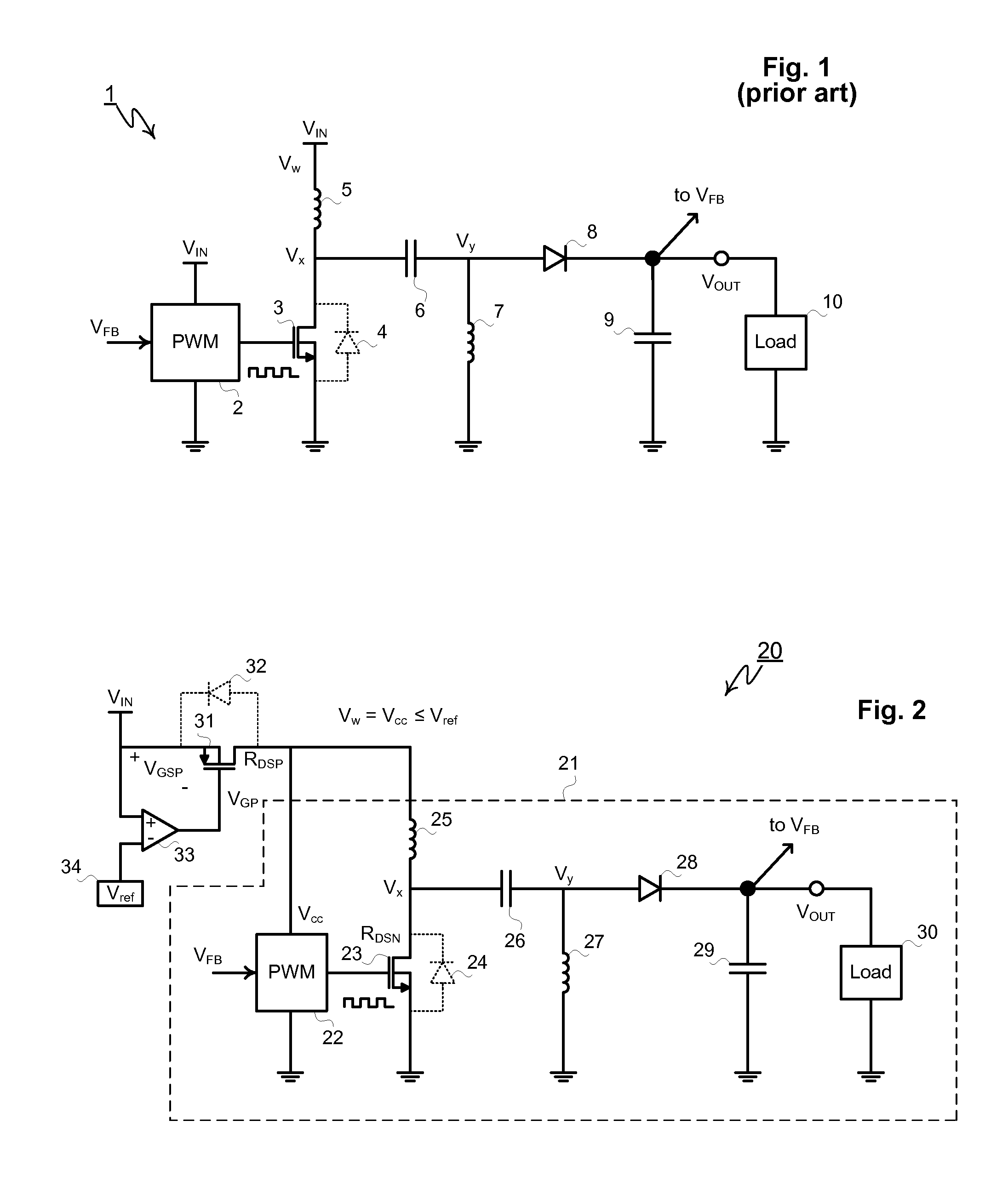
[0021]One means to extend the voltage range of the SEPIC converter is to utilize an over-voltage protection, i.e. OVP, circuit that disconnects the converter from the input in the event the input voltage exceeds a pre-specified value. In converter 20 of FIG. 2, SEPIC converter 21 is protected by P-channel MOSFET 31 controller by comparator 33 which compares the input voltage VIN to a reference voltage Vref. Reference voltage 34 may be implemented using a bandgap reference, Zener diode, a series of forward biased diodes or any other well known voltage reference technique, or a scaled multiple of said voltage. P-channel MOSFET 31 includes reverse-biased intrinsic P-N diode 32 with its anode tied to VIN and its cathode connected to the input to converter 21.

[0022]SEPIC converter 21 comprises a PWM control circuit 22, N-channel power MOSFET 23 with intrinsic drain-to-source diode 24, high-side inductor 25, capacitor 26, low-side inductor 27, rectifier d...


PUM


Abstract

A SEPIC converter with over-voltage protection includes a high-side inductor that connects a node Vw to a node Vx. The node Vx is connected, in turn to ground by a power MOSFET. The node Vx is also connected to a node Vy by a first capacitor. The node Vy is connected to ground by a low-side inductor. A rectifier diode further connects the node Vy and a node Vout and an output capacitor is connected between the node Vout and ground. A PWM control circuit is connected to drive the power MOSFET. An over-voltage protection MOSFET connects an input supply to the PWM control circuit and the node Vw. A comparator monitors the voltage of the input supply. If that voltage exceeds a predetermined value Vref the comparator output causes the over-voltage protection MOSFET to disconnect the node Vw and the PWM control circuit from the input supply.

Description

BACKGROUND OF THE INVENTION[0001]Most DC to DC switching voltage regulators such as the Buck converter and boost converter are capable of only regulating a voltage above or below a given input but not capable of both step up and step down regulation. A SEPIC (single ended primary inductor converter) is a DC-DC converter which allows the output voltage to be greater than, less than, or equal to the input voltage. The output voltage of the SEPIC is controlled by the duty cycle of the control transistor. The largest advantage of a SEPIC over the buck-boost converter is a non-inverted output (positive voltage). SEPICs are useful in applications where the battery voltage can be above and below the regulator output voltage. For example, a single Lithium ion battery typically has an output voltage ranging from 4.2 Volts to 3 Volts. If the accompanying device requires 3.3 Volts, then the SEPIC would be effective since the battery voltage can be both above and below the regulator output volt...

Claims


Application Information

Patent Timeline
IPC IPC(8): G05F1/44H02H3/20
CPCH02M1/32H02M3/005H02H3/20G05F1/46H02M2003/1557H02M3/1557
Inventor WILLIAMS, RICHARD K.D'ANGELO, KEVINCOLES, CHARLES
Owner ADVANCED ANALOGIC TECHNOLOGIES INCORPORATED
Learn More