Length measurement system

a measurement system and measurement method technology, applied in the field of length measurement system, can solve the problems of affecting the accuracy of measurement, too many noises to find values without smoothing, and the inability of the above-mentioned method to cope with any of the size (length) and roughness measurements, so as to prevent the measurement of values, the effect of improving the accuracy of measurement and facilitating the setting

Active Publication Date:
View PDF6 Cites 17 Cited by
  • Summary
  • Abstract
  • Description
  • Claims
  • Application Information

AI Technical Summary

Benefits of technology

[0077]According to the present invention, therefore, when in size (length) measurements or roughness measurements, the smoothing parameter has come to be set more easily than any conventional methods, thereby the accuracy of measurements is more improved.
[0078]Furthermore, according to the present invention, size (length) or roughness values have come to be calculated even from images having low signal quality (signal S / N ratio is low or the number of signal integrations is less). Thus measured values are prevented from variations that might otherwise occur due to image processings. Consequently, it is possible to obtain measured values that are more closer to their true values.
[0079]Furthermore, the present invention can reduce the number of signal integrations required for improving the image quality more significantly than any conventional methods, so the beam irradiation onto samples is reduced and accordingly, sample damages are reduced. In addition, the number of images to be obtained is also reduced, so the total measurement or inspection time is reduced, thereby the measurement throughput is improved.

Problems solved by technology

If the noise level goes over a certain value, however, the above methods cannot cope with any of the size (length) and roughness measurements.
This is because there are too many noises to find values without smoothing.
What is considered to be a problem here is that deformation or distortion of signal profiles to be caused by averaging or smoothing in the vertical or normal direction of an object pattern edge is much more serious than the influence to signal profiles to be caused by averaging in the parallel or tangential direction of the pattern edge.
Thus shapes of signal profiles themselves come to be damaged.

Method used


Image

  • Length measurement system
  • Length measurement system
  • Length measurement system

Examples


first embodiment

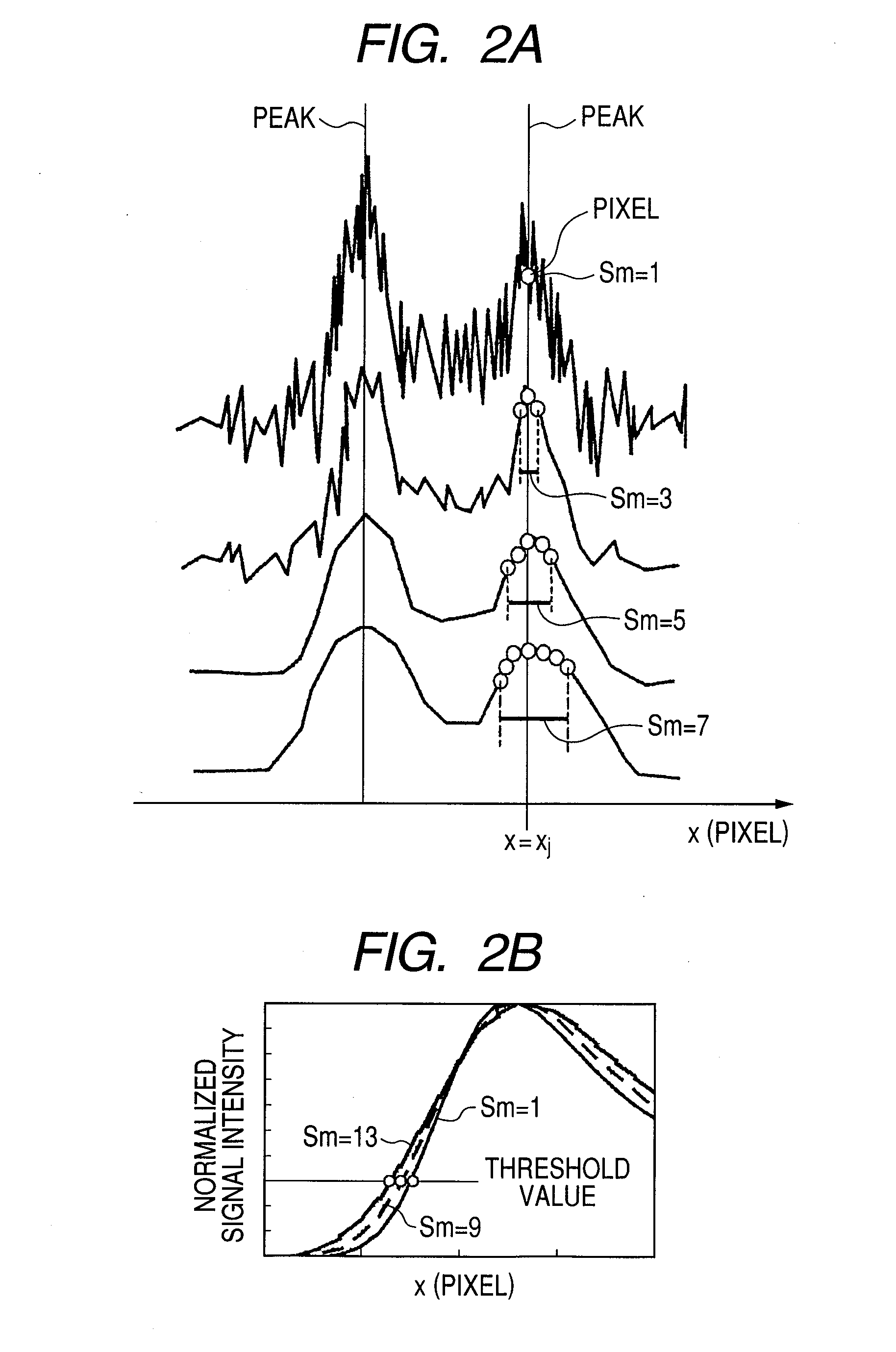
[0110]In this first embodiment, there will be described one of the objects of the present invention, which is related to size (length) measurements described in the section of “SUMMARY OF THE INVENTION”. The method selects an Sm value that will less affect size (length) values by figuring out positions and size (length) values of edge points in cases in which the Sm value is 1 and not 1. In this embodiment, the method is applied to measurement results of a line pattern observed through an electron microscope capable of measuring lengths, that is, through a CD-SEM.

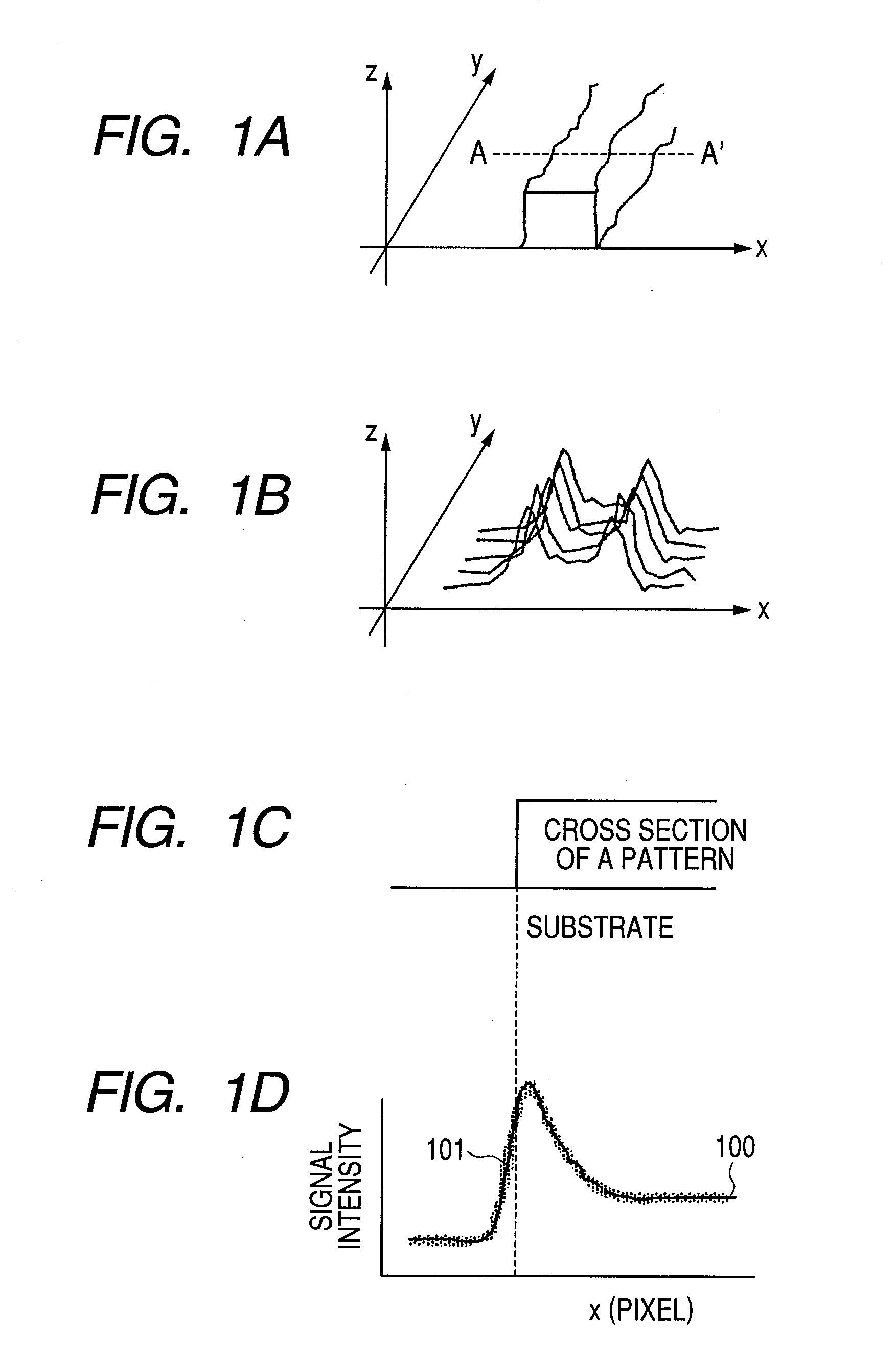
[0111]This first embodiment will be described with reference to FIGS. 11 through 15. FIG. 11 shows a typical signal profile obtained from an image through pattern observation. FIG. 12 shows an explanatory view of an employed inspection system with respect to its configuration. FIG. 13 is a CD-SEM image of a pattern analyzed in this first embodiment, that is, an explanatory view of the two-dimensional distribution data of a ...

second embodiment

[0130]In this second embodiment, there will be described another one of the objects of the present invention described in the section “SUMMARY OF THE INVENTION”. The object relates to a method that estimates a size (length) value at Sm=1, that is, a size (length) value that might be obtained without smoothing by fitting the dependency of a size (length) value on the Sm value with a function. In this embodiment, the method is applied to line pattern measurement results obtained by using an electron microscope capable of measuring lengths, that is, by using a CD-SEM.

[0131]This second embodiment will be described with reference to FIGS. 12, 12, and 16. FIG. 12 shows an explanatory view of a configuration of an employed inspection system. FIG. 13 shows an explanatory view of two-dimensional distribution data of a CD-SEM image of a pattern analyzed in this second embodiment, that is, that of a secondary electron signal, as well as a processing region defined on the image. FIG. 16 shows a...

third embodiment

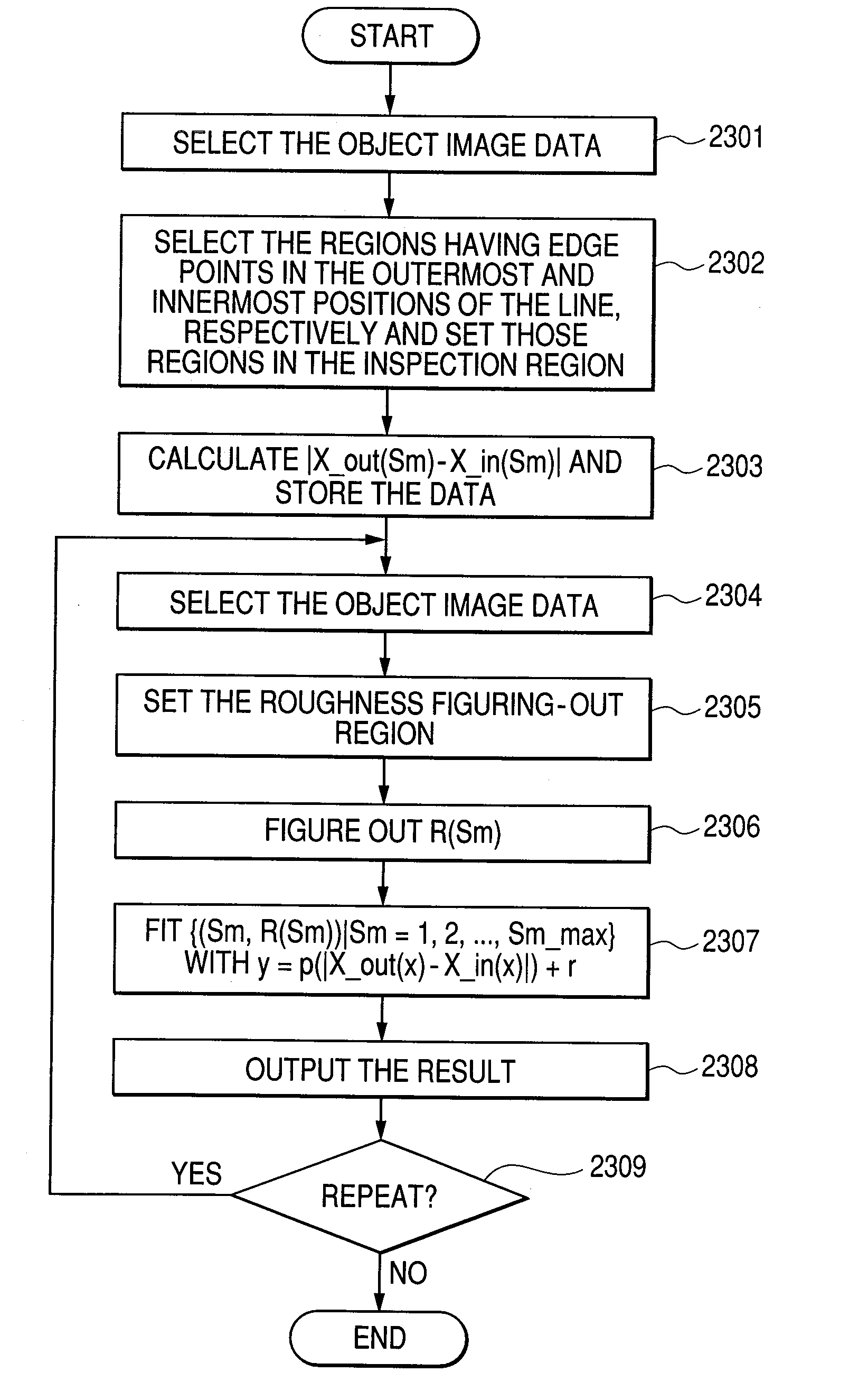
[0141]In this third embodiment, there will be described still another one of the objects of the present invention, which is related to the roughness measurement described in the section of “SUMMARY OF THE INVENTION”. The object is a measurement method applied to line pattern measurement results obtained by using an electron microscope capable of measuring lengths, that is, by using a CD-SEM. According to the method, at first, the widest region and the narrowest region that appear like bands on an image that is equivalent to pattern edges are selected, then the dependencies B(Sm) and N(Sm) of each edge point position on the Sm value are calculated with respect to each of those widest and narrowest band-like regions. Then, according to the result, a difference between those calculated Sm values is calculated to select an object Sm value.

[0142]This third embodiment will be described with reference to FIGS. 12, 17, 18, and 19. FIG. 12 shows an explanatory view of a configuration of an e...


PUM


Abstract

Disclosed herewith is a length measurement system, which obtains a value closer to its true one when figuring out the size and edge roughness of a pattern from a noise-included pattern image. Among plural band-like regions representing a portion around an edge in an image respectively, the system calculates the dependency of the edge point position on the image processing parameter at each of a narrow width band-like portion and a wide width band-like portion to calculate an image processing condition that calculates each measured value closer to its true value or estimates the true value itself.

Description

CLAIM OF PRIORITY[0001]The present application claims priority from Japanese patent application JP 2007-212532 filed on Aug. 17, 2007, the content of which is hereby incorporated by reference into this application.FIELD OF THE INVENTION[0002]The present invention relates to a method for measuring sizes of patterns or rough shapes of pattern edges through non-destructive inspections with use of a scanning microscope and a method for inspecting micro patterns through measurements of pattern size fluctuations, as well as an inspection system and an evaluation method employed for the inspection system.BACKGROUND OF THE INVENTION[0003]In the industrial fields of semiconductors and other related products, there have been demands to more accurate measurements of micro pattern shapes along with the progress of the microfabrication in pattern processing sizes. In addition to those pattern sizes, it has also been required to evaluate the micro roughness of pattern edges (edge roughness) that ...

Claims


Application Information

Patent Timeline
Patent Type & Authority Applications(United States)
IPC IPC(8): G06K9/00G06V10/44
CPCG06K9/4604G06T7/0006G06T2207/30148G06T7/60G06T2207/10061G06T7/0085G06T7/13G06V10/44
Inventor YAMAGUCHI, ATSUKOYAMAMOTO, JIROKAWADA, HIROKI
Why Eureka
Try Eureka