Bearing tooth gears for wind turbine applications

a technology of bearings and cam followers, applied in the direction of gearing details, gearing, machines/engines, etc., can solve the problems of not being able to meet the load rating of bearings or cam followers found in catalogs, and achieve the effect of lowering replacement costs, lowering scheduled maintenance costs, and high compressive stress

Inactive Publication Date: 2009-02-19
KOLEOGLOU ALEX
View PDF46 Cites 22 Cited by
  • Summary
  • Abstract
  • Description
  • Claims
  • Application Information

AI Technical Summary

Benefits of technology

[0024]By providing a gearmotor and gear box at ground level, there should be lowered scheduled maintenance costs due to easy access to the generator and related controls, with related lowered replacement costs of any failed generator or controls. Therefore easy access is provided to working generator and gear box parts for a wind turbine on the ground, instead of having to maintain the generator and gear box parts typically 300 feet up in the air in the vicinity of the rotating wind turbine blades.
[0025]The use of bearing teeth with a round periphery introduces high compressive stress in the contact region as the bearings mesh. For co-planar meshing bearing tooth gears, the contact configuration is a line contact. For orthogonal meshing bearing tooth gears the contact configuration is a point contact. To reduce this contact stress concentration, which can exceed 300,000 pounds per square inch (psi), which exceeds the working stress of high alloy steels, the peripheral geometry of the bearing teeth themselves is changed from round to a regular polygon such as a square or a hexagon, or an external contact housing of these shapes is press fit onto the round bearing periphery. In preferred embodiments, a hexagonal periphery is used for co-planar meshing bearing tooth gears whereas a square periphery is used for orthogonal meshing bearing tooth gears. These changes convert the contact configuration of both species to a flat surface area contact thereby greatly reducing contact region stress concentration at the expense of introducing a small amount of sliding friction. The latter can be mitigated by using a solid lubricant coating on the contact surfaces.

Problems solved by technology

Bearings or cam followers found in catalogs as standard parts may not be available in load ratings high enough to configure gear sets or drives for wind turbines which today have ratings as high as five megawatts (approximately 6700 horsepower).

Method used


Image

  • Bearing tooth gears for wind turbine applications
  • Bearing tooth gears for wind turbine applications
  • Bearing tooth gears for wind turbine applications

Examples


Embodiment Construction

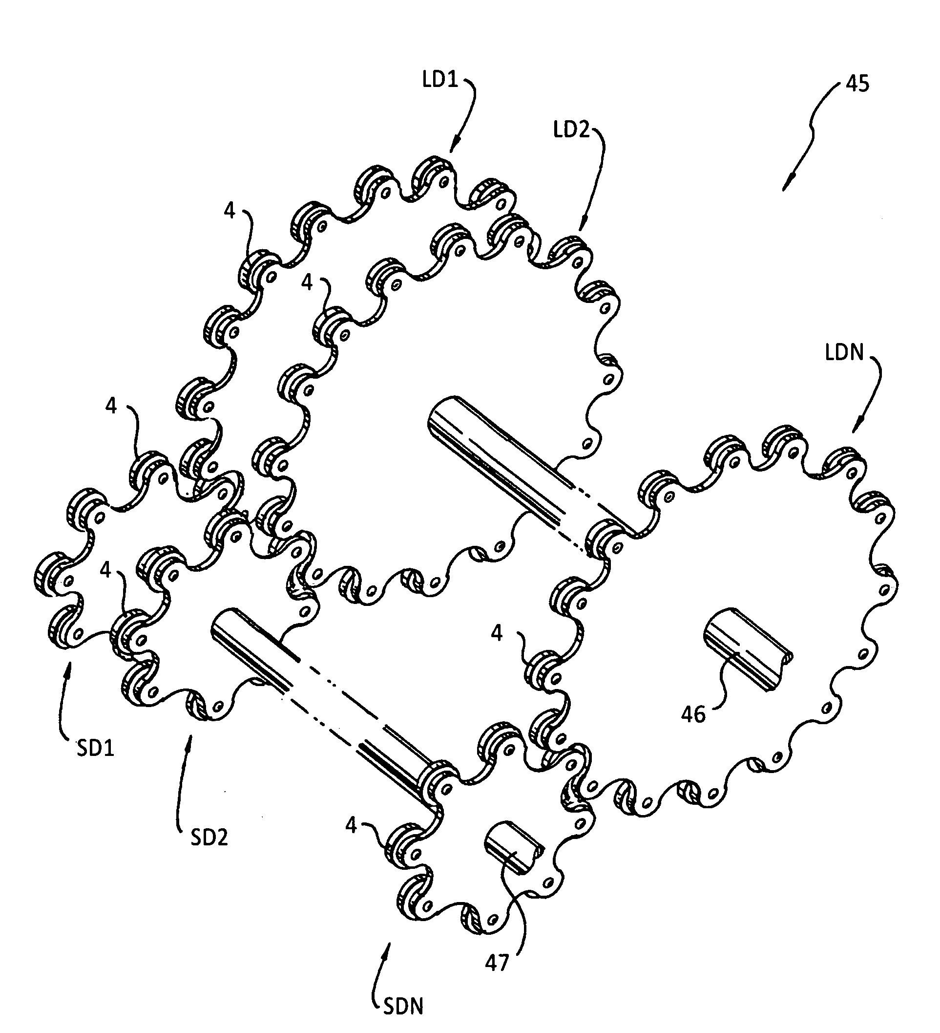
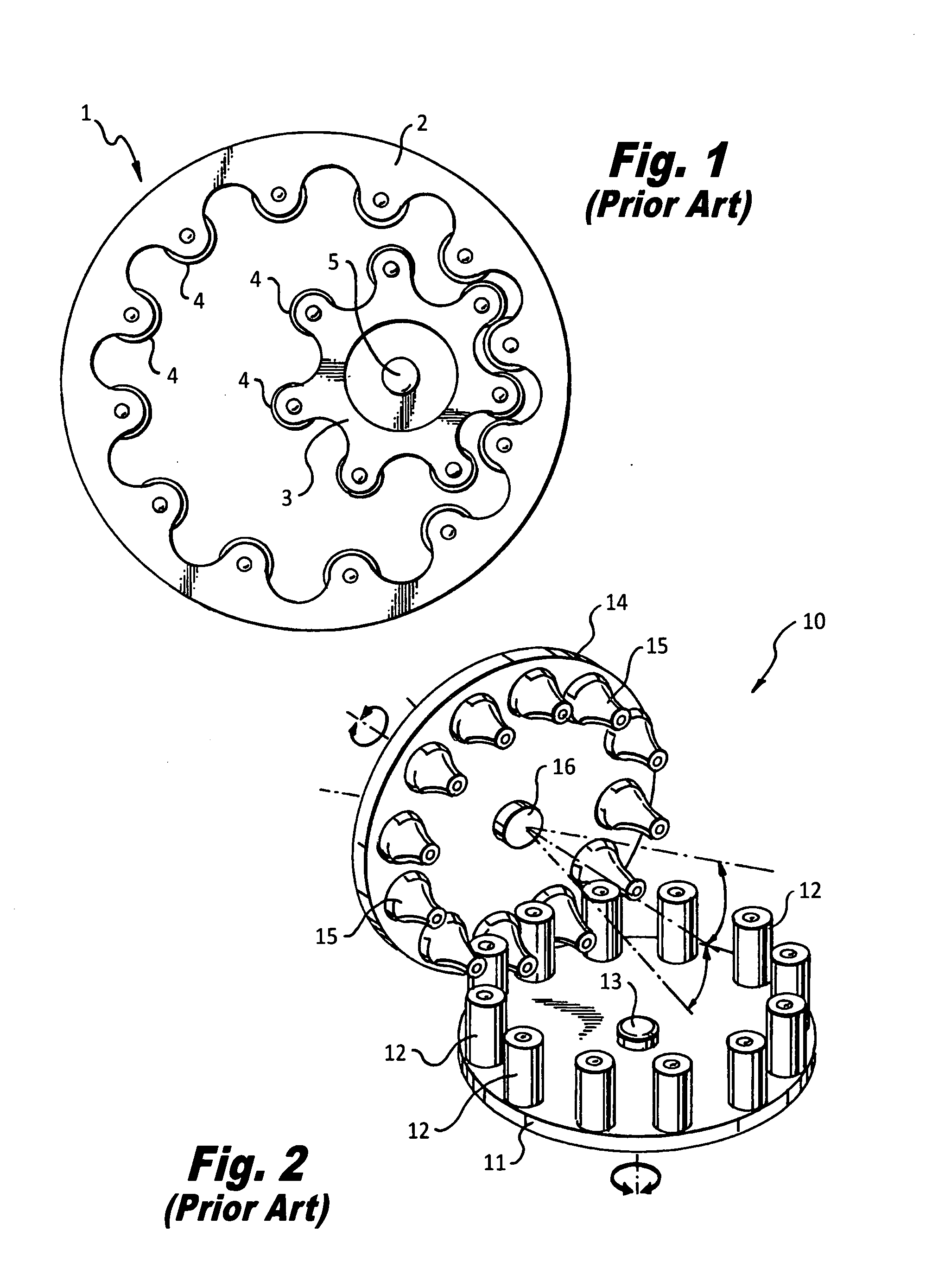
[0045]Two types of prior art bearing tooth gear sets are shown in FIGS. 1 and 2. Gear set 1 is planar, consisting of spur gear disk 3 with bearings 4 mounted at its periphery at a regular pitch engaged with ring disk 2 also with bearings 4 at the same pitch. Shaft 5 is at the center of gear disk 3.

[0046]A right-angle drive 10 is shown in FIG. 2. Vertical disk 14 turns on shaft 16 and carries bearings 15 with contoured surface on one face. Horizontal disk 11 turning on shaft 13 carries cylindrical bearings 12 at the same pitch as bearings 15 with which they are engaged. Note that the angle between shafts 13 and 16 can deviate as shown by the arrows while still transmitting torque adequately in the desired direction.

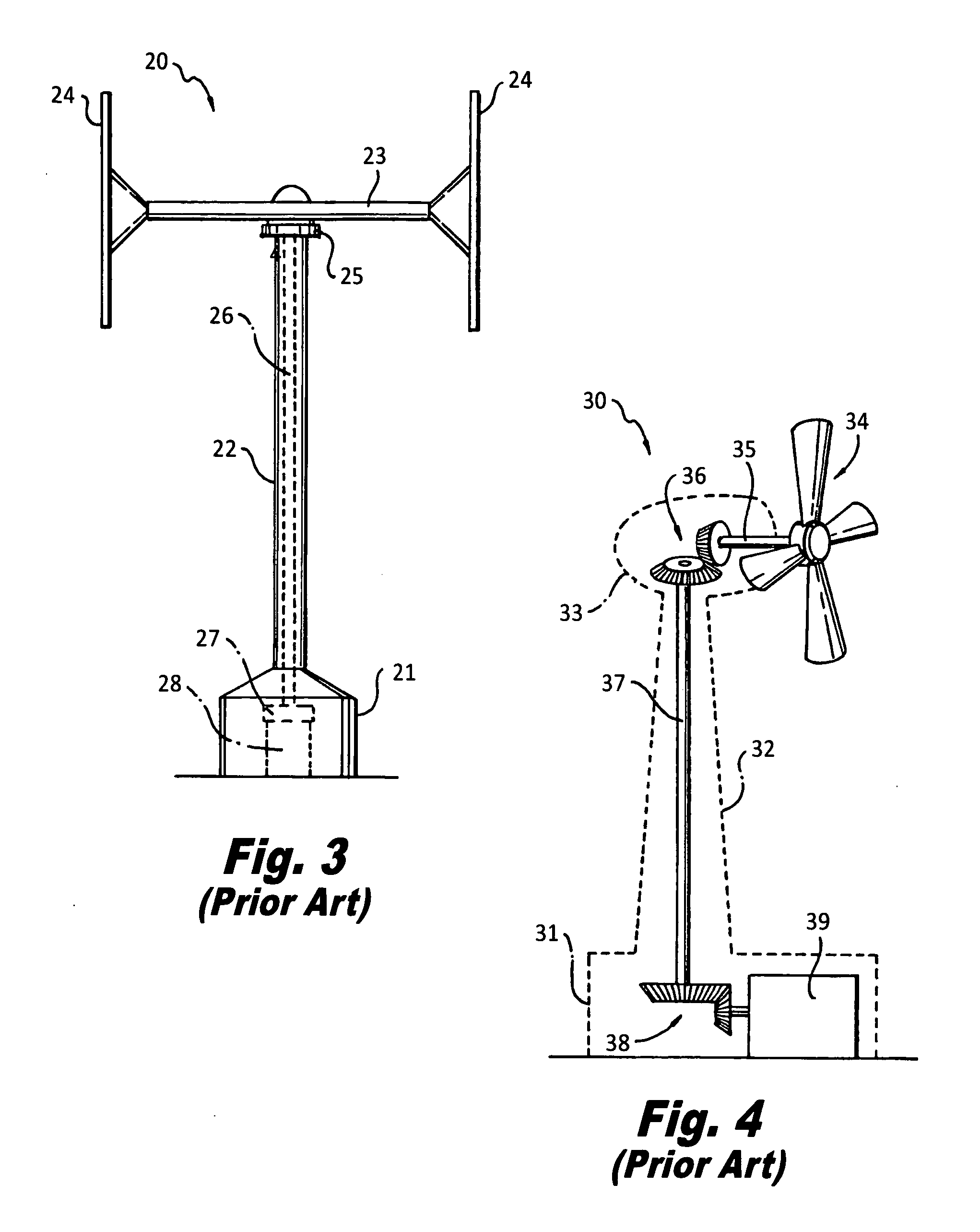
[0047]Two examples of prior art wind turbines with base mounted generators are shown in FIGS. 3 and 4.

[0048]FIG. 3 shows a vertical axis wind turbine 20 with top bearing assembly 25 atop tower 22 permitting crossbar 23 to turn by action of airfoils 24. Crossbar 23 is attac...


PUM


Abstract

A horizontal axis wind turbine includes a vertically extending tower 117 having a rotatable long shaft 121. A bottom end of the long shaft drives an electric generator 122 and a top end of the long shaft is connected to a power output gear assembly of a bearing tooth angle drive 120. The power output gear assembly is engaged with a power input gear in the bearing tooth angle drive 120. The power input gear is connected by a drive shaft 86 through a preferably planetary gear drive 119 to blades 106 of a wind turbine to receive power from the wind turbine and to deliver torque to the long shaft 121 to drive the generator 122. The planetary gear teeth preferably have flat surfaces providing contact with related gear teeth.

Description

RELATED APPLICATIONS[0001]This application is based upon provisional application Ser. No. 60 / 965,068 filed Aug. 17, 2007 and upon provisional application Ser. No. 61 / 011,905 filed Jan. 22, 2008 and claims priority and benefit under 35 U.S.C. 119(e) therefrom. These applications are incorporated by reference herein.FIELD OF THE INVENTION[0002]The present invention relates to reliable and efficient horizontal axis wind turbines.BACKGROUND OF THE INVENTION[0003]Since the proliferation of modern horizontal axis wind turbines over the past decade, experience and operating statistics have demonstrated that the speed-increasing gearbox has been the source of most field failures. The most prevalent design of current wind turbines places a nacelle atop a tall tower, the nacelle housing a gearbox driven by the turbine propeller as well as the generator attached to the gearbox. To service the gearbox involves personnel entering the nacelle to perform the task of repair or replacement of the ge...

Claims


Application Information

Patent Timeline
Patent Type & Authority Applications(United States)
IPC IPC(8): F16H13/06F16H15/48
CPCF03D11/02Y02E10/722F16H55/10F05B2260/403F03D9/25F03D15/00F03D15/10F03D80/70Y02E10/72
Inventor KOLEOGLOU, ALEX
Owner KOLEOGLOU ALEX
Why Eureka
Try Eureka