
Formed filter element

a filter element and forming technology, applied in the field of filter elements, can solve the problems of limited ability to achieve certain filtration attributes such as pore size, basis weight, thickness, permeability and efficiency, and conventional technologies are not suitably flexible to effectively accommodate the range of particle sizes. , to achieve the effect of excellent characteristics and low pressure drop

Inactive Publication Date: 2009-02-26
DONALDSON CO INC
View PDF103 Cites 105 Cited by
  • Summary
  • Abstract
  • Description
  • Claims
  • Application Information

AI Technical Summary

Benefits of technology

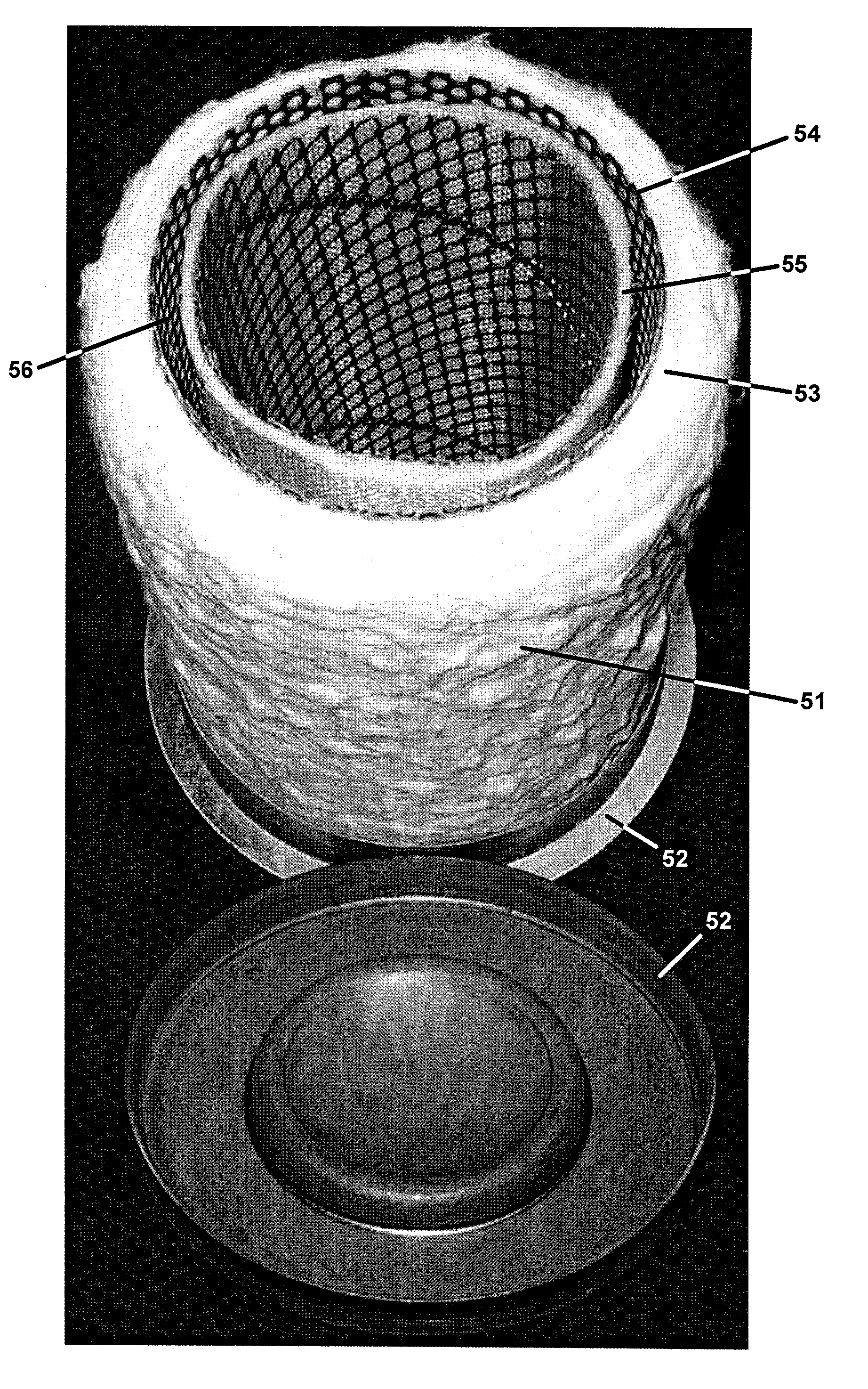
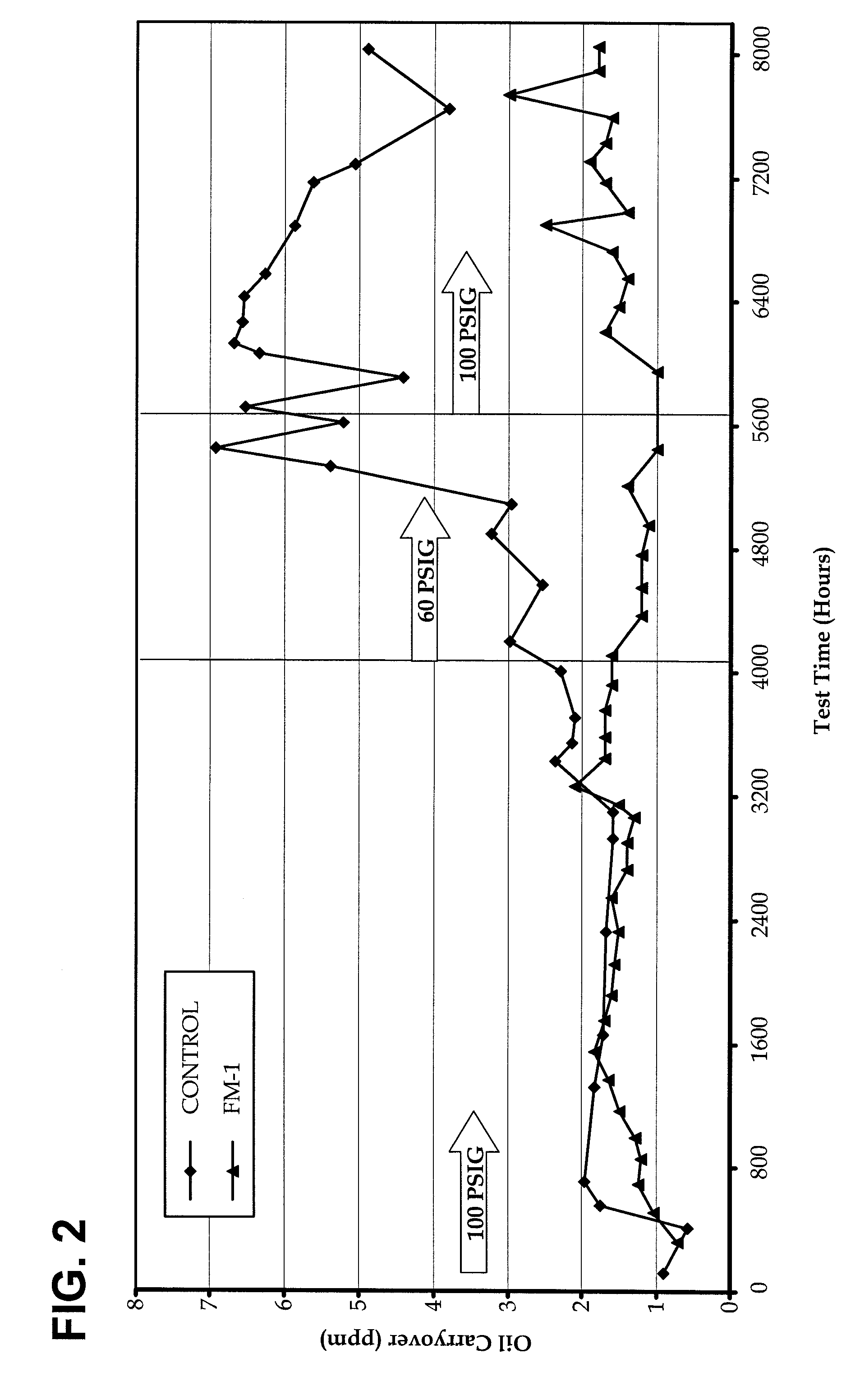
[0016]The filter media of this invention is particularly useful in separating an entrained liquid aerosol from a mobile air phase. The media of the invention has excellent characteristics of removal of oily aerosol, for example, from a fluid stream that is largely made of air and aerosol. Thus, when a stream of air having between 2000 and 9000 ppm of oily aerosol per ppm of total fluid, more typically about 7000 ppm of oily aerosol per ppm of total fluid, is passed through the filter at 60 to 100 psi, less than or equal to 2 ppm of the aerosol remains in the air stream after filtration a

Problems solved by technology

Such thin flexible filter media have found a number of useful applications, however, such layers have limits in their applicability.
The ability to achieve certain filtration attributes such as pore size, basis weight, thickness, permeability and efficiency are limited by the manufacturing techniques used to make the paper layers and by the components useful in such layers.
Because aerosols, as an example, may be as small as 1 nm diameter or as large as 1 mm (W. Hinds, Aerosol Technology: Properties, Behavior, and Measurement of Airborne Particles 8, 2nd ed., © 1999 J. Wiley & Sons), conventional technologies are not suitably flexible to effectively accommodate the range of particle sizes in which aerosols may be encountered in air.
Such concentrations are not filtered with high efficiency using the thin filters of the prior art; thus, multiple layers are usually employed.
Further, these filter media suffer from resin migration during the filter media life, which in turn causes a loss of porosity.
In use, this loss of porosity is evidenced by increased pressure drop across the filter, clogging of pores, and cracking of the filter, thus leading to early filter failure.
Further, these filter media are brittle and may shatter under challenging conditions, leading to catastrophic failure.
Finally, the above filter making technique has a practical limit of about 5.0 mm thickness, such that the ability to make thicker media for use with different aerosols or adaptation for other filtration applications is not provided.

Method used


Image

  • Formed filter element
  • Formed filter element
  • Formed filter element

Examples


example 1

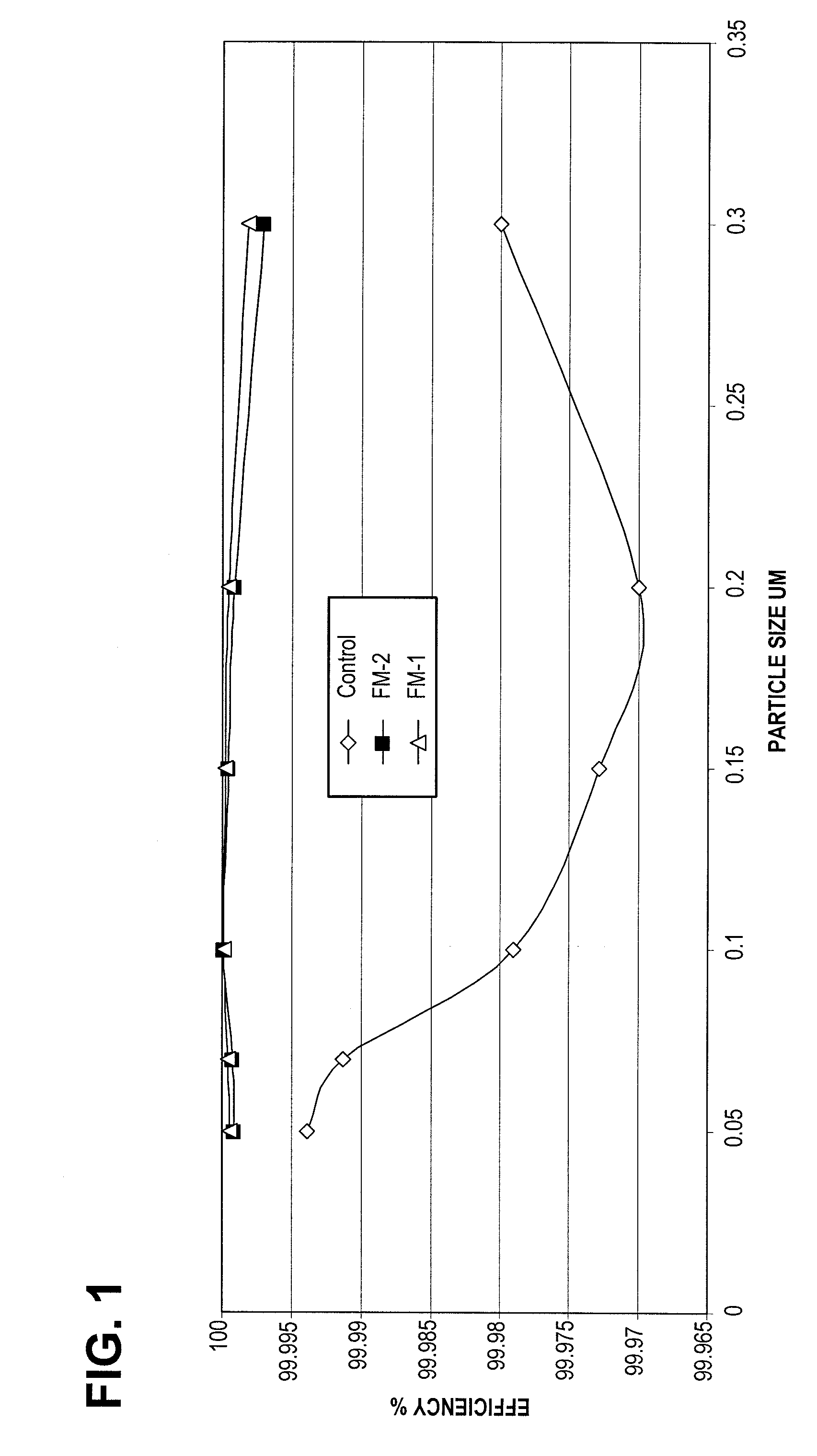
[0079]A filter medium of the invention, FM-1, was made using the following technique. Into 250 gallons of untreated tap water was mixed Advansa 271P bicomponent fiber (obtained from EXSA Americas, New York, N.Y.), Evanite #610 glass fiber, and Evanite #608 glass fiber (both obtained from the Evanite Fiber Corporation of Corvallis, Oreg.) such that the relative weight of the components are as shown in Table 1. Mixing was carried out with a 2HP rotating paddle mixer for between 30 and 45 minutes to obtain an aqueous slurry of fibers. The slurry was then vacuum formed onto a 5.25″×9″ perforated metal cylinder by completely immersing the cylinder in the slurry and holding it under a vacuum of approximately 20 inches Hg for 3-10 seconds.

[0080]The formed media was then retracted from the slurry and vacuum was maintained for 15-30 s. The media was removed from the vacuum fixture and placed in a vented oven. The oven temperature was set to 300° C. Residence time in the oven was approximatel...

example 2

[0082]A filter medium of the present invention, hereafter referred to as FM-2, was made using the filter making process of Example 1. The components of the filter slurry are shown in Table 2.

TABLE 2Components of FM-2FibersWt. (g)DuPont 271 fiber (14μ)980Evanite ® glass fiber #610 (2.8μ)200Evanite ® glass fiber #608 (0.8μ)420

After the oven drying step, FM-2 was 0.84 cm thick. FM-2 was found to have a basis weight of 1187 g / M2. The initial air permeability of FM-2 was determined to be 1.4 feet / minute (fpm).

example 3

[0083]A filter medium of the present invention, hereafter referred to as FM-3, was made using the filter making process of Example 1. The components of the filter were bicomponent fibers and carbon particles, added to the slurry at a ratio of approximately 1:1 by weight. The bicomponent fibers were DuPont-271 fibers. The carbon particles were Calgon MD5695, 50-200 mesh activated carbon particles from a coconut powder source, obtained from the Calgon Carbon Company of Pittsburgh, Pa. The particles were mixed directly into the slurry with no prior treatment or washing. After the oven drying step, the filter was analyzed for weight percent of the components. The components of the filter are shown in Table 3. Micrographs of the inside and side views of FM-3 are shown in FIGS. 7e and 7f.

TABLE 3Components of FM-3ComponentWt. %DuPont-271 (14μ)49.95MD5695, 50-200 mesh carbon particles50.05

[0084]The available surface area of the MD5695 particles and the FM-3 filter media containing 50% MD569...


PUM

PropertyMeasurementUnit
Temperatureaaaaaaaaaa
Lengthaaaaaaaaaa
Lengthaaaaaaaaaa

Abstract

A filter medium for use in filtering a mobile fluid made from at least a bicomponent fiber. Other fibers, particles, or other materials can also be entrained in the filter medium. The filter medium has a substantial thickness compared to filters of the prior art. The fiber length and diameter dimensions are selected to obtain desired filter characteristics including thickness, basis weight, pore size, filtration efficiency, pressure drop, burst strength, and manufacturing efficiency. Further, a multilayer filter medium can be provided with ease. Each layer can have a different composition, pore size, basis weight, and so forth, thus providing the ability to build multiple functionality into the filter media of the invention.

Description

CROSS REFERENCE TO RELATED APPLICATIONS[0001]This application claims priority from U.S. Provisional Patent Application Ser. No. 60 / 903,179, filed Feb. 23, 2007 and is hereby incorporated by reference in its entirety.FIELD OF THE INVENTION[0002]The invention relates to a filter element that can be used for general filtration. One filtration application is removing a liquid or solid particulate from a mobile fluid and methods of manufacturing the element. In one embodiment of the invention, the filter element is used to remove an oily or aqueous / oil liquid aerosol or particulate entrained in a gaseous or air mobile fluid. In such an embodiment, the aerosol entrained in the fluid contacts the media, coalesces, and drains from the media leaving the mobile fluid free of the entrained liquid aerosol particulate. The liquid accumulates in the media and under the effect of gravity, drains from the element and can be reserved.BACKGROUND OF THE INVENTION[0003]Cellulosic, synthetic and mixed c...

Claims


Application Information

Patent Timeline
IPC IPC(8): B01D39/14B01D46/00C02F1/00B05D3/02
CPCB01D39/1615Y10T29/49826B01D39/2024B01D39/2048B01D39/2058B01D39/2062B01D39/2065B01D39/2089B01D2239/0216B01D2239/025B01D2239/0407B01D2239/064B01D2239/086B01D2239/1225B01D2239/1233B01D2239/1241B01D39/163
Inventor ISRAEL, JOSEPHDUNN, III, EUGENE F.
Owner DONALDSON CO INC
Learn More