
Signal processing device

a technology of signal processing and processing circuit, which is applied in the field of signal processing devices, can solve the problems of increasing the cost of installing such hardware and driving circuit, blurring of an image, and general shot image blurring, so as to prevent the device from becoming a large size

Inactive Publication Date: 2009-02-26
NITTO OPTICAL CO LTD
View PDF3 Cites 2 Cited by
  • Summary
  • Abstract
  • Description
  • Claims
  • Application Information

AI Technical Summary

Benefits of technology

[0011]The advantage of the invention is to provide a signal processing device realizing a practical image processing of restoring image data as well as preventing the device from becoming a large size.
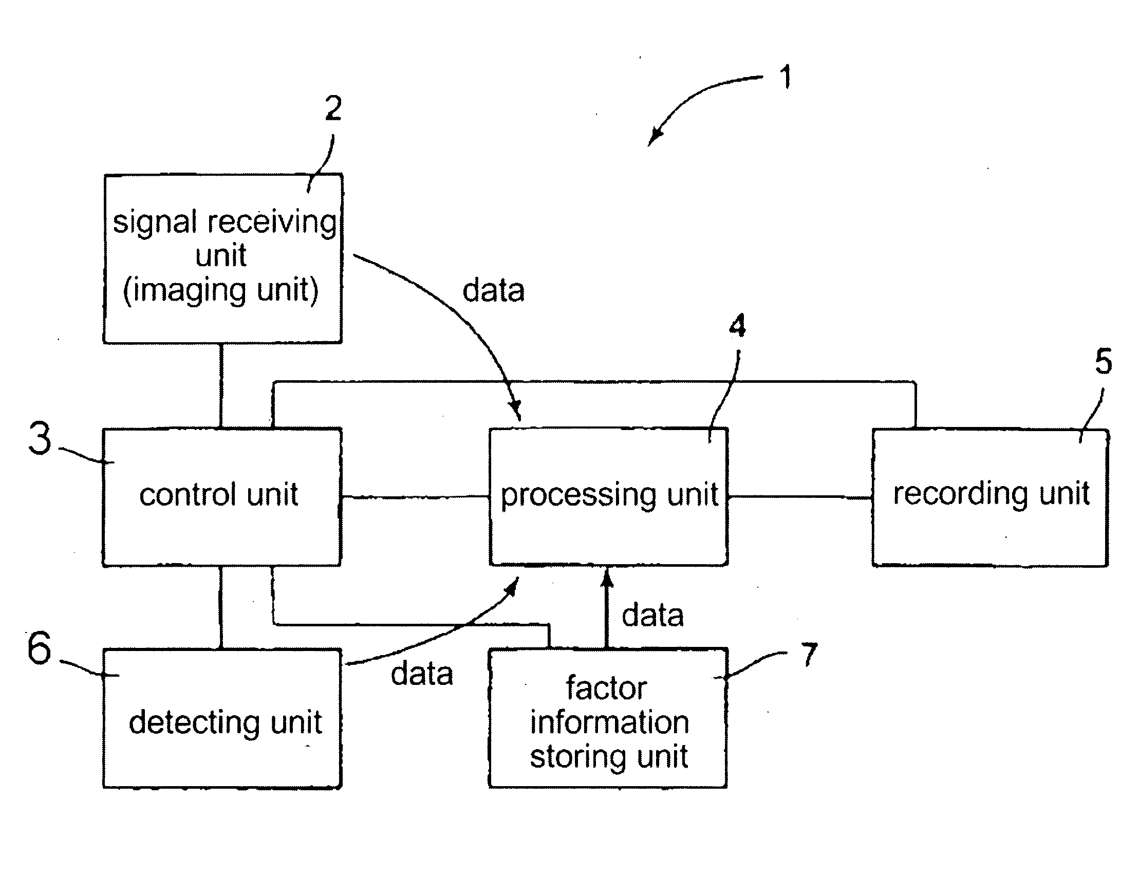
[0012]According to an aspect of the invention, a signal processing device comprises:an processing unit that restores one of a signal before fluctuation, a signal which should have been intrinsically obtained, and signal data which is approximated to these signals (these signals are called as an original signal data) from an initial signal (called as fluctuated data) which has fluctuated like deterioration. A fluctuated data region storing fluctuated data and a restored data region storing signal data (restored data) restored every restoring process are installed. The processing unit repeats the following processes for producing data in the restored data region at the process completion as original signal data. Namely, the processing unit transfers energy of the fluctuated data from the fluctuated data region to the restored data region using fluctuation-factor information data, which is a fluctuation factor, so as to produce restored data; and substitutes residual data in the fluctuated data region remained through the data transfer with the fluctuated data.
[0013]In this aspect of the invention, it is premised that the original signal data is changed to the fluctuated data accompanied with the fluctuation-factor information data. Hence, using the fluctuation-factor information data as the same filter can certainly restore the original signal in the restored data region if the energy of the fluctuated data is transferred to the restored data region. Here, the fluctuated data stored in the fluctuated data region may be data obtained by processing the fluctuated data with keeping the energy state constituting the fluctuated data unchanged. The restored data stored in the restored data region may be data obtained by processing the restored data with keeping the energy sate constituting the restored data unchanged. Further, “transfer” includes transfer of energy value as literal interpretation from the fluctuated data region to the restored data region, removing the energy from the fluctuated data region and producing new energy in the restored data region. Further, the fluctuated data region and the restored data region include a region temporarily formed or permanently formed or both of them (the same hereafter.)
[0014]In addition to the aspect of the invention, during the repeating process, the energy transferred to the restored data region may be added to the restored data already stored in the restored data region every repeating and the residual data is approximated to zero. If the residual data approaches zero, most energy in the fluctuated data region is transferred to the restored data region, approaching the restored data to the original data.
[0015]According to other aspect of the invention, a signal processing device comprises: a processing unit that restores original signal data including a plurality of elements from fluctuated data including a plurality of elements. A fluctuated data region storing fluctuated data and a restored data region storing data restored every restoring process are installed. The processing unit repeats the following processes for each element. Namely, the processing unit transfers elemental energy existed in one element of the fluctuated data from the fluctuated data region to the restored data region using the barycenter of response characteristic function held by fluctuation-factor information data, which is a fluctuation factor; removes the element energy corresponding to the transferred element energy using fluctuation-factor information data from the fluctuated data region; applies the previous processes to other element in series so as to produce restored data in the restored data region; and substitutes residual data in the fluctuated data region remained through the removing with the fluctuated data. Further, the processing unit adds the element energy transferred to the restored data region to the restored data every repeating, approaches the residual data to zero and produces data formed in the restored data region at the completion of the processes as original signal data.
[0016]In the other aspect of the invention, it is premised that the original data signal is changed to the fluctuated data accompanied with the fluctuation-factor information data. Most energy of fluctuated data is transferred to the restored data region using inversed numbers of the barycenter values (values in an area where energy is mostly concentrated) of response characteristic function held by fluctuation-factor information data, which is the same filter. The element energy corresponding to the transferred element energy is removed using fluctuation-factor information data from the fluctuated data region and the energy value of residual data (called as residual energy amount) approaches to zero. These processes can certainly restore the original signal data in the restored region. Here, the fluctuated data stored in the fluctuated data region may be data obtained by processing the fluctuated data with keeping the energy state of each element constituting the fluctuated data unchanged. The restored data stored in the restored data region may be data obtained by processing the restored data with keeping the energy state of each element constituting the restored data unchanged. Further, “transfer” includes transfer of energy value as literal interpretation from the fluctuated data region to the restored data region, removing the energy from the fluctuated region and producing new energy corresponding to the energy in the restored data region. Further, the response characteristic function includes an impulse response function and a unit response function. The impulse response function becomes a point spread function if signal data is image data.

Problems solved by technology

A blur of an image is mainly due to hand jiggling (camera shaking) when taking a picture, various aberrations in optics, lens distortion and the like.
Further, signals from a sound, an x-ray photograph, a microscopic picture, an earth quake wave form and the like except a general shot image might have been also blurred and deteriorated due to fluctuation and other causes.
Further, installing such hardware and a driving circuit needs to increase a cost.
Namely, following two issues cause difficulty of producing a restored image in actual; though inversed transformation of the barycenter value Ga of the point spread transfer function theoretically produces a restored image.
First, the gained point spread transfer function is extremely weak in handling noises and information errors about a blur and slight variation of them greatly affects the values of the function.
This variation results in a disadvantage in that a restored image produced by the inversed transformation is far from a stabilized image without hand jiggling and out of use in actual.
But calculated values for such estimation run into astronomical numbers, actually yielding a high risk of remaining unsolved.
These issues regarding an image emerge from general various kinds of signal data.
It is difficult to restore a signal by using the inverse transformation if the gained transfer function is inaccurate or even if it is accurate.
Further, it is impossible to gain a perfectly accurate transfer function if processing objects in nature.

Method used


Image

  • Signal processing device
  • Signal processing device
  • Signal processing device

Examples


Embodiment Construction

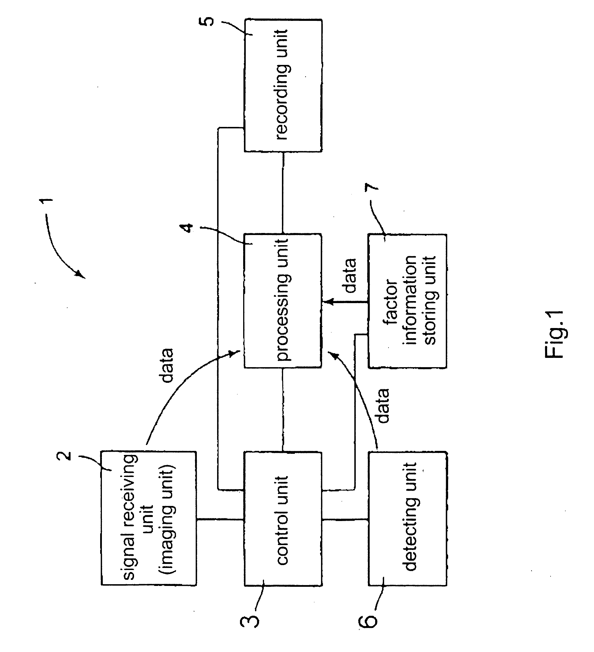
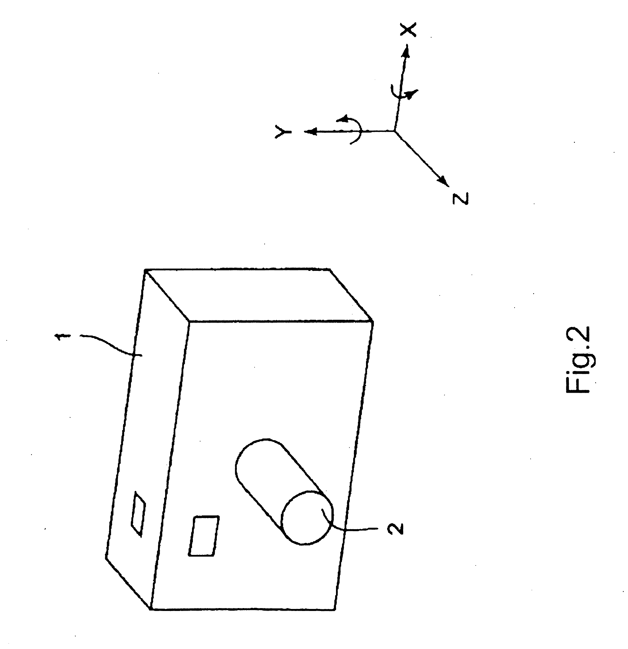
[0037]The following reference numerals are used in the following description of the present invention.[0038]1: signal processing device,[0039]2: signal receiving unit (imaging unit),[0040]3: control unit,[0041]4; processing unit,[0042]5; recording unit,[0043]6; detecting unit,[0044]7; factor information storing unit,[0045]G; fluctuation-factor information data (data of information about deterioration factors),[0046]Ga; barycenter value of point spread function,[0047]Img′; initial image data (shot image),[0048]Img; data of correct and intrinsic image without blurring (original image),[0049]E; initial image pixel energy,[0050]Fn: transferred pixel energy,[0051]Rn: restored energy,[0052]cE; correction energy,[0053]En: residual energy amount (object energy to be processed),[0054]Emax: maximum value of residual energy amount,[0055]X: predetermined value of residual energy amount,[0056]Tn: pixel energy amount removed from original image data region,

[0057]A signal processing unit 1 accordi...


PUM


Abstract

A signal processing device includes a system of system of circuit processing in essence while avoiding large sized device under restoring fluctuated signals such as deterioration and the like. The signal processing unit includes a processing unit that restores one of a signal before fluctuation, a signal which should have been intrinsically obtained, and signal data which is approximated from these signals from an initial signal which has fluctuated like deterioration. A fluctuated data region storing fluctuated data and a restored data region storing signal data (restored data) restored every restoring process are installed. The processing unit repeats the following processes in order to produce data formed in the restored data region at the completion of processing as original signal data. The processing unit transfers energy of the fluctuated data from the fluctuated data region to the restored data region using fluctuation-factor information data, which is a fluctuation factor, and produces restored data; and substitutes residual data in the fluctuated data region remained through the data transfer for the fluctuated data.

Description

[0001]This application is based upon and claims the benefit of priority from Japanese Patent Application No. 2006-028006, filed on Jun. 2, 2006, disclosure of which is incorporated herein in its entirety by reference.FIELD OF THE INVENTION[0002]The present invention relates a signal processing device.BACKGROUND OF THE INVENTION[0003]It is conventionally known that an image is blurred when taking a picture with a signal processing device such as camera and the like. A blur of an image is mainly due to hand jiggling (camera shaking) when taking a picture, various aberrations in optics, lens distortion and the like.[0004]In order to stabilize an image, there are two methods, moving lens and electronic processing. As a method of moving a lens, for example, the patent document 1 discloses a method of stabilizing an image by detecting hand jiggling and moving a predetermined lens in response to hand jiggling. As a method of electronic processing, the document 2 discloses a method of produ...

Claims


Application Information

Patent Timeline
Patent Type & Authority Applications(United States)
IPC IPC(8): H04N5/228H04N23/40
CPCH04N5/23248H04N2101/00H04N5/23264H04N23/682H04N23/68
Inventor TAKAHASHI, FUMINORI
Owner NITTO OPTICAL CO LTD
Learn More