Method and apparatus for raising the spark energy in capacitive ignition systems

a capacitive ignition and spark energy technology, applied in the direction of generator generated ignition energy, engine ignition, other installations, etc., can solve the problems of small or no addition of energy at low speed, conventional ignition systems have difficulty in providing sufficient spark energy, etc., to achieve good charge level of capacitors, improve efficiency, and reduce cost

Inactive Publication Date: 2009-03-05
SEM AB
View PDF1 Cites 2 Cited by
  • Summary
  • Abstract
  • Description
  • Claims
  • Application Information

AI Technical Summary

Benefits of technology

[0009]The method and apparatus according to the invention gives a possibility for instance to optimise the number of turns of the charge winding for high engine speeds and at the same time it gives a possibility to keep a good charge level on the capacitor at lower engine speeds.
[0010]This is achieved by adding two relatively low cost components to the conventional circuit—namely one additional rectifier diode and one transistor which can short circuit the charge winding. Due to the fact that the charging pulse from the charge winding is relatively long at low engine speeds it is possible by means of switching said transistor on and off at a certain frequency to make the charging procedure for the capacitor more efficient at the same time as the additional energy is controlled so that the charge voltage over the capacitor is not reaching harmful levels.
[0011]In the future environmental demands could require small engines of the type here discussed to be provided with fuel injection systems in stead of carburettors. This gives better possibilities to supervise and control the combustion, i.e. you get more power, less fuel consumption, cleaner exhaust gases etc. One problem with switching to fuel injection systems is that these systems require considerably more energy. The fuel has as we know to be pressed into the cylinder during the compression phase. This is usually done by means of an electrically powered injector which requires considerable energy. Due to the fact that at mobile, portable systems, in view of the weight, one does not wish to add a battery, the flywheel related generator must consequently deliver this energy. Irrespective of how one chooses to design this generator it will be necessary to optimise the same for delivering a lot of energy to an injection system at considerably lower voltage than what is required for charging of the charge capacitor of the CDI system. Also this problem can be addressed by means of the method according to the invention, i.e. a low voltage winding could by means of the method according to the invention generate a “high voltage” to the charge capacitor.
[0012]An additional advantage with the method and apparatus according to the invention is that the existing so called environmental friendly fuels (e.g. E85) with different additions of ethanol could be used without the operation being affected by as serious problems as with a conventional ignition system. The start of a cold engine with some kind of ethanol fuel requires higher spark energy than the start with pure gasoline due to the fact that the vaporisation of ethanol is definitely inferior and therefore has a less good inflammability.
[0013]An additional advantage with the invention is that said additional transistor which will be apparent from the following could be used in order to limit or completely turn off the charging function. This fact could be used in order to provide a so called “one-push-stop”-function at which an instantaneous pressing of a button is detected which is used for completely short-circuiting the charge winding by means of the transistor so that no energy reaches the charge capacitor which causes the engine to stop.

Problems solved by technology

Especially at low speed, e.g. at start of such accessories, conventional ignition systems have difficulties to deliver sufficient spark energy in order to ensure a quick and reliable start.
But the method only gives small or no additions of energy at low speed.

Method used


Image

  • Method and apparatus for raising the spark energy in capacitive ignition systems
  • Method and apparatus for raising the spark energy in capacitive ignition systems
  • Method and apparatus for raising the spark energy in capacitive ignition systems

Examples


Embodiment Construction

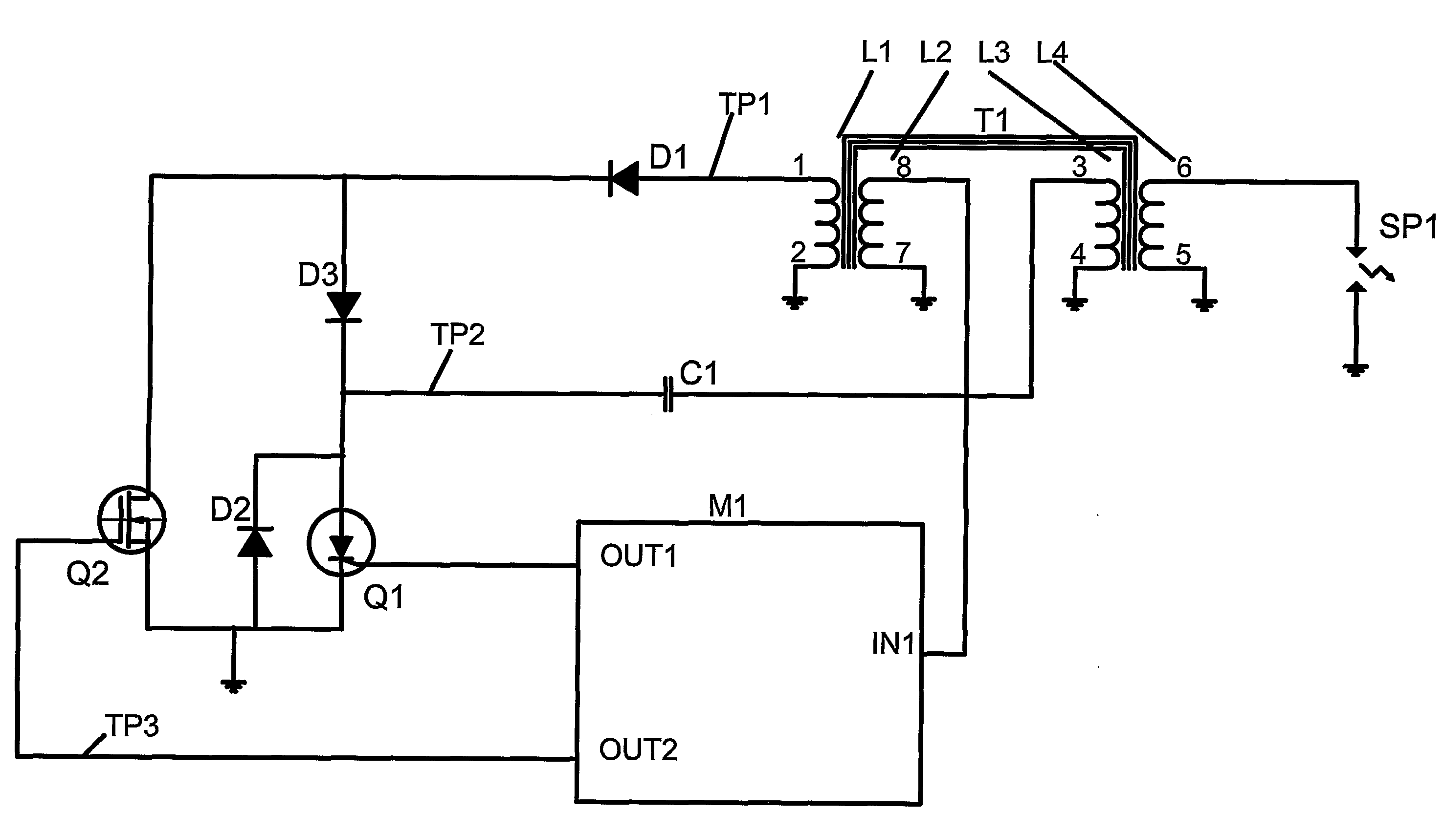
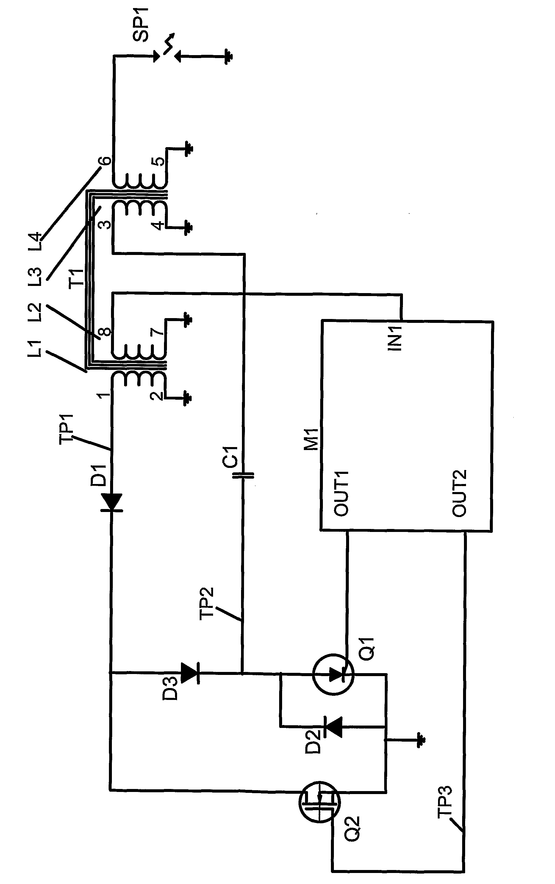
[0020]In FIG. 1 is schematically shown a circuit diagram in a somewhat simplified form of a typical CDI-system for small engines which has been modified according to the invention. An iron core T1 provided with four conventionally arranged windings is magnetised by means of one or several magnets integrated in the flywheel which at the rotation of the flywheel will sweep past the end portions of the iron core. The variant with several magnets could be used for providing from a generally point of view a more powerful generator which in addition to the function as ignition voltage generator also could be used for other purposes for example fuel injection systems or handle heating on chain saws. The relative magnet movement induces a voltage in the windings L1-4 according to the following.

[0021]The winding L1 is the so called charge winding in which is induced a voltage which is used for the spark generation as such. The winding L1 is via one of its end points 1 connected via the recti...


PUM


Abstract

The present invention refers to an apparatus for raising the spark energy in capacitive ignition systems comprising at least one charge winding (L1) which via a first rectifier device (D1) charges a charge capacitor (C1) connected to the primary winding of an 5 ignition voltage transformer in order to provide said primary winding with energy for generation of a spark characterised in that additionally a second rectifier device (D2) and a switching device (Q2) are arranged in such a way that the switching device periodically can short circuit the charge winding and thereby increase the charge of the charge capacitor at low engine speeds.

Description

TECHNICAL FIELD[0001]The present invention refers to a method and an apparatus for raising the spark energy, especially in small so called “Capacitive Discharge Ignition (CDI)” systems without batteries for combustion engines at which the ignition voltage is generated by means of a generator and associated control circuitry connected to or integrated in the flywheel.[0002]The invention can be implemented without the necessity of changing external conditions as e.g. the intensity of magnetisation, iron cores etc. in an existing generator. More generally the idea of the invention could be used in order to create a more powerful voltage generation especially at small mobile internal combustion engine systems.BACKGROUND ART[0003]The method and the apparatus have special application at small, mobile, manually started internal combustion engine powered devices as e.g. accessories of different types as chainsaws, lawnmowers and outboard motors and the like. Especially at low speed, e.g. at...

Claims


Application Information

Patent Timeline
Patent Type & Authority Applications(United States)
IPC IPC(8): F02P3/02
CPCF02P1/086F02P3/09F02P3/0876F02P3/0838F02P3/093
Inventor OLSSON, JOHAN
Owner SEM AB
Why Eureka
Try Eureka