Voltage converting circuit and battery device
- Summary
- Abstract
- Description
- Claims
- Application Information
AI Technical Summary
Benefits of technology
Problems solved by technology
Method used
Image
Examples
Embodiment Construction
[0059]In the following, an embodiment of the present invention will be explained based on the figures.
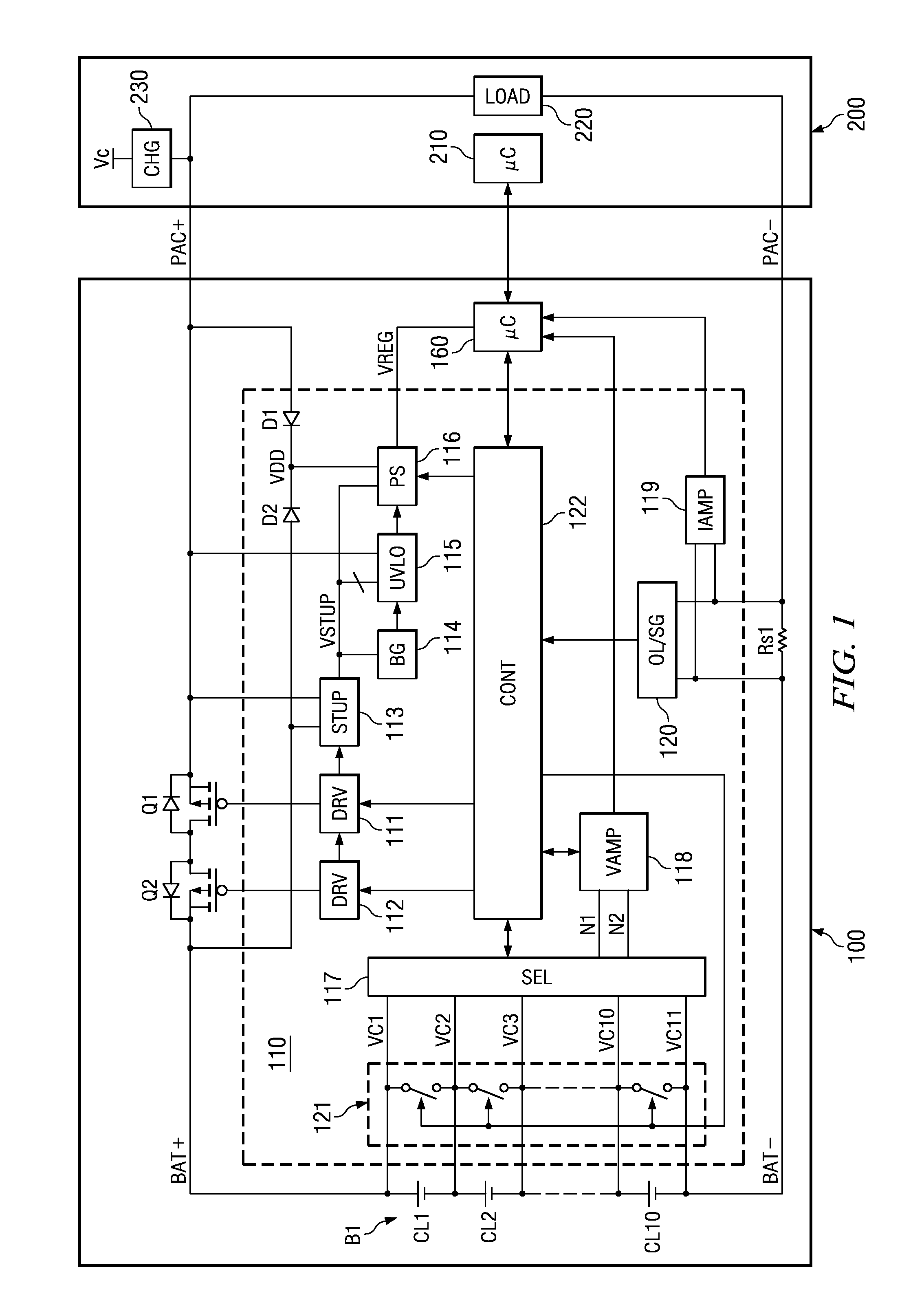
[0060]FIG. 1 is a diagram illustrating a configuration example of the battery device disclosed in the embodiment of the present invention.
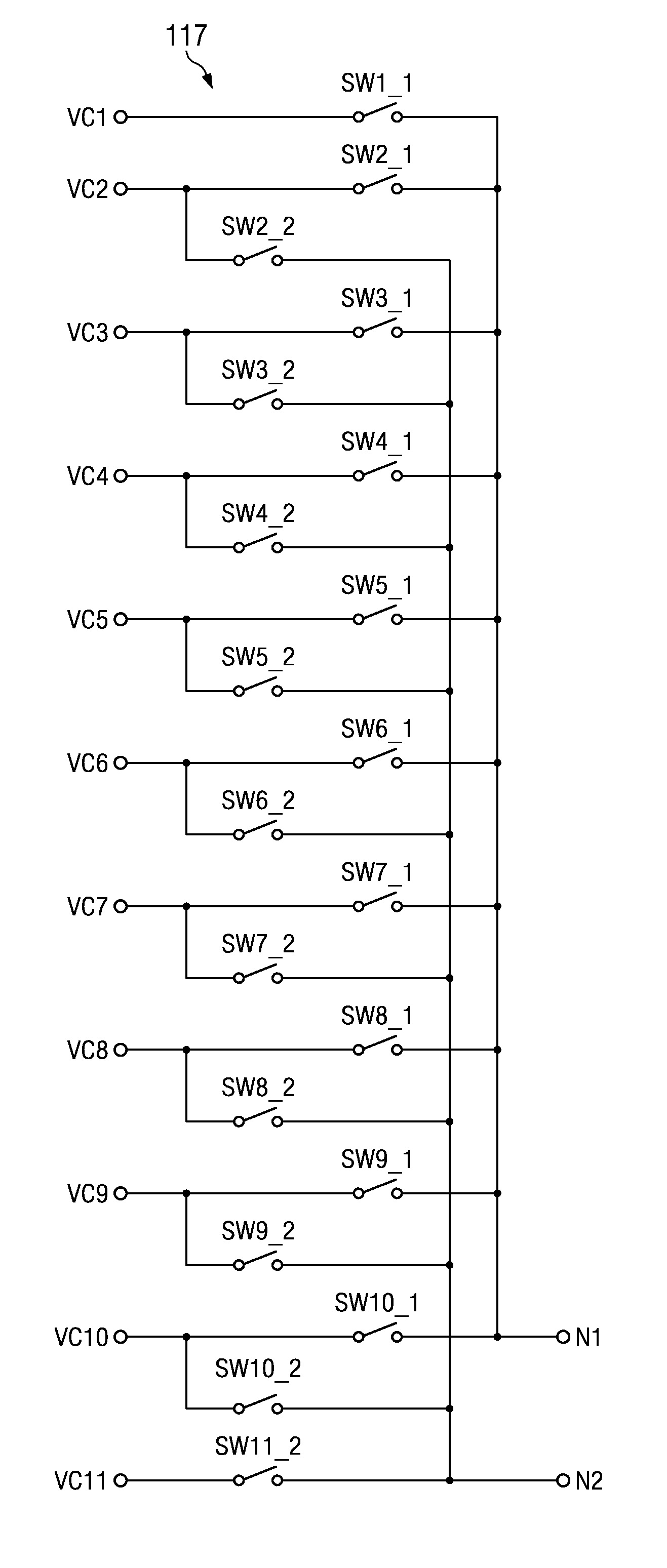
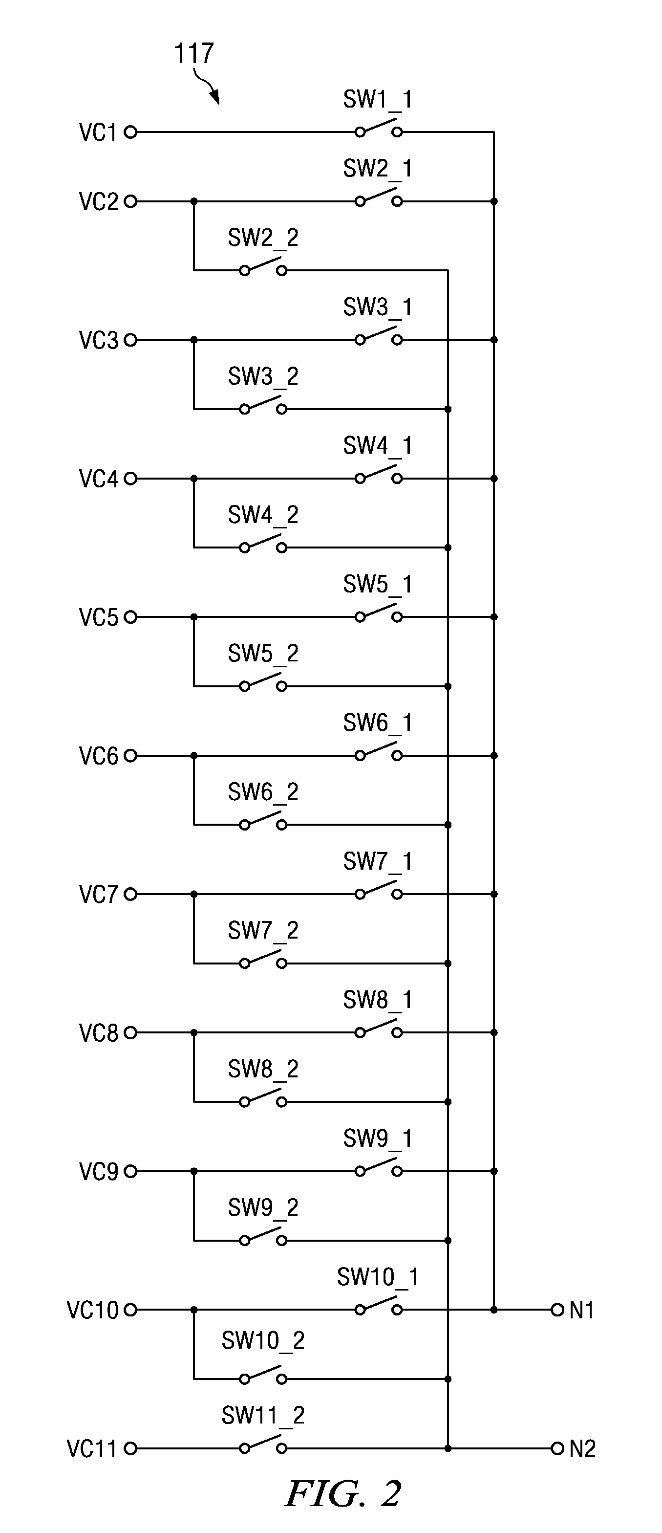
[0061]Battery device 100 shown in FIG. 1 has p-type MOS transistors Q1, Q2, battery B1, resistor Rs1 for current detection, analog front end part (AFE part) 110, and microcomputer 160. AFE part 110 includes diodes D1, D2, drive circuits 111, 112 of MOS transistors Q1, Q2, setup circuit 113, reference voltage generating circuit 114, low-voltage operation lock circuit 115, power supply circuit 116, selection circuit 117, voltage amplification circuit 118, current amplification circuit 119, overcurrent / short circuit detection circuit 120, current bypass circuit 121, and control circuit 122.
[0062]The circuit block including selection circuit 117 and voltage amplification circuit 118 is an example of the voltage converting circuit of the present invent...
PUM
 Abstract
Description
Claims
Application Information
 - R&D
- Intellectual Property
- Life Sciences
- Materials
- Tech Scout
- Unparalleled Data Quality
- Higher Quality Content
- 60% Fewer Hallucinations
Browse by: Latest US Patents, China's latest patents, Technical Efficacy Thesaurus, Application Domain, Technology Topic, Popular Technical Reports.
© 2025 PatSnap. All rights reserved.Legal|Privacy policy|Modern Slavery Act Transparency Statement|Sitemap|About US| Contact US: help@patsnap.com


