Optical scanning apparatus, and image forming apparatus

a scanning apparatus and image technology, applied in the field of optical scanning apparatuses, can solve the problems of changing the lens is subject to ambient changes, and the beam spot size on the scanned surface changes, so as to reduce the variation in the beam spot size and stable the effect of the beam spot siz

Inactive Publication Date: 2009-03-05
RICOH KK
View PDF12 Cites 17 Cited by
  • Summary
  • Abstract
  • Description
  • Claims
  • Application Information

AI Technical Summary

Benefits of technology

[0023]It is a general object of the present invention to provide an optical scanning apparatus and an image forming apparatus in which the aforementioned problems are eliminated. A more specific object is to provide an optical scanning apparatus using an elliptical diffra

Problems solved by technology

However, it is also well known that a resin lens is subject to ambient changes, particularly a temperature change, as a result of which the shape or refractive index of the lens may vary.
Consequently, the optical characteristics of a resin lens, particularly its power, may vary from its design values, resulting in a change in the beam spot size on a scanned surface.
Such characteristics change is also a cause of the beam spot size change.
One problem associated with the use of multiple diffracting surfaces is the drop in diffraction efficiency, i.e., a decrease in optical transmission efficiency due to the development of diffracted light other than diffracted light of desired diffraction orders.
Such a problem would not occur if the optical element is molded as per its design values; however, in actual molding process, processing variations are inevitable, and so is the decrease in diffraction efficiency.
Generally, resin is a poorer transmitter of light than normal glass.
If the transmission efficiency of the resin lens additionally decreases due to the drop in diffraction efficiency, a situation may develop where

Method used


Image

  • Optical scanning apparatus, and image forming apparatus
  • Optical scanning apparatus, and image forming apparatus
  • Optical scanning apparatus, and image forming apparatus

Examples


example 1

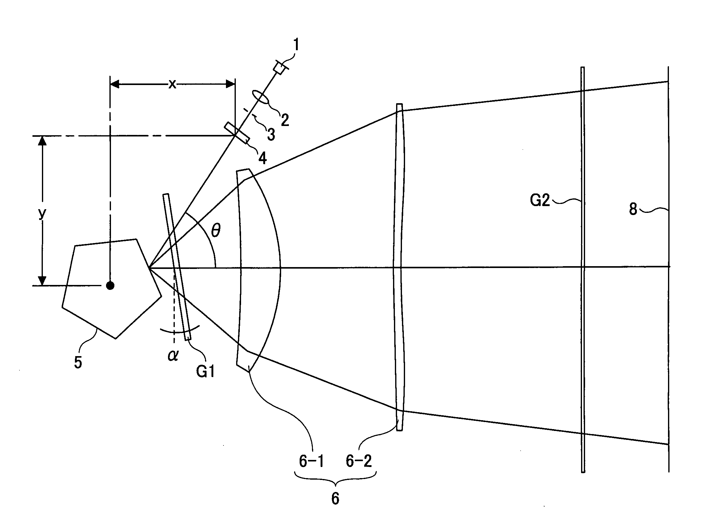
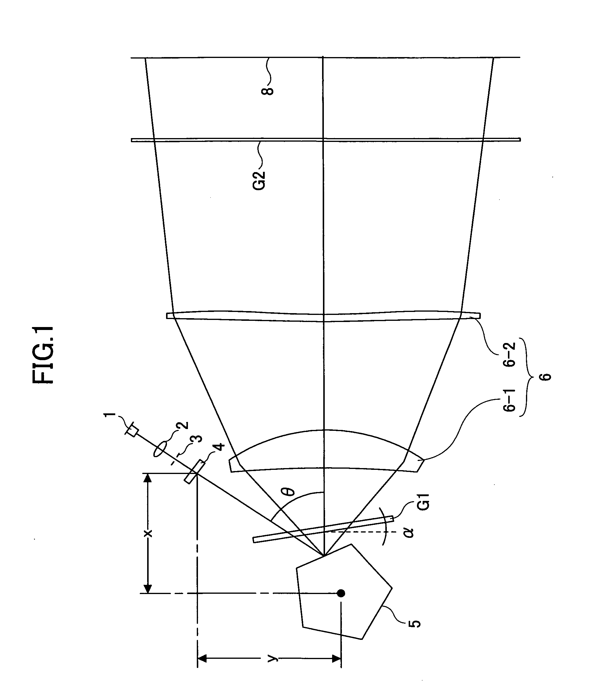
[0135]The semiconductor laser 1 and the coupling lens 2 are fixedly retained on a retaining member with a linear coefficient of expansion of 1.0×10⁻⁵.

[0136]The coefficients of the diffracting surface of the anamorphic optical element 4 are such that Cy=2.95×10⁻³ and Cz=1.747×10⁻².

[0137]The amount of change in the beam waist position at 45° C. with respect to the reference temperature of 25° C. is as follows:

[0138]Main scan direction: −0.03 mm

[0139]Sub-scan direction: −0.13 mm

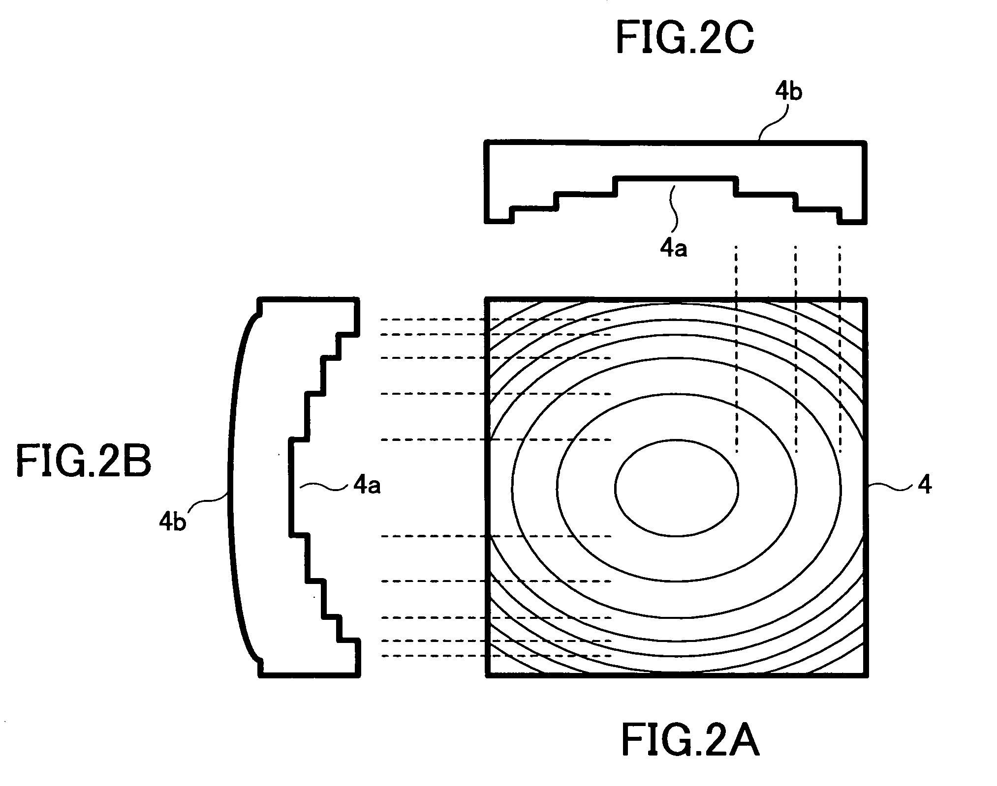
[0140]Thus, it can be seen that satisfactory corrections are made in both the main scan direction and the sub-scan direction. The ellipticity is 0.169, so that the diffracting surface can be processed relatively easily.

[0141]Such processability leads to an enhanced accuracy in the diffracting surface and contributes to the maintenance of quality of the diffracting function.

[0142]The inventive concept of increasing the ellipticity of an elliptical shape on a diffracting surface may be applied regardless of the ma...

example 2

[0152]The semiconductor laser 1 and the coupling lens 2 are fixedly retained on a retaining member with a linear coefficient of expansion of 5.0×10⁻⁶.

[0153]The coefficients of the diffracting surface of the anamorphic optical element 4 are such that Cy=3.38×10⁻³ and Cz=1.758×10⁻².

[0154]The amount of the beam waist position change at 45° C. with respect to the reference temperature of 25° C. is as follows:

[0155]Main scan direction: −0.03 mm

[0156]Sub-scan direction: 0.1 mm

[0157]Thus, it can be seen that satisfactory corrections are made in both the main scan direction and the sub-scan direction. The ellipticity in this case is 0.192, so that processing is easier than in the case of Example 1.

example 3

[0158]The ellipticity can be increased merely by making the coupling lens with resin.

[0159]Specifically, in this example, resin 1 shown in Table 1 is used as the material for the coupling lens. The coupling lens is disposed such that its front principal point is located 35.06 mm away from the light-emitting portion of the semiconductor laser 1, so that a collimating action is obtained at the focal distance of 35.06 mm. The semiconductor laser 1 and the coupling lens 2 are fixedly retained on a retaining member with a linear coefficient of expansion of 5.0×10⁻⁵.

[0160]The coefficients of the diffracting surface of the anamorphic optical element 4 are such that Cy=7.8×10⁻³ and Cz=1.55×10⁻².

[0161]The amount of the beam waist position change at 45° C. with respect to the reference temperature of 25° C. is as follows:

[0162]Main scan direction: 0.02 mm

[0163]Sub-scan direction: 0.1 mm

[0164]Thus, it can be seen that satisfactory corrections are made in both the main scan direction and the su...


PUM


Abstract

An optical scanning apparatus includes a semiconductor laser and a first optical element that are fixed on a single continuous member. A second optical element, which is a diffraction optical element, has a diffracting surface in which an elliptical groove is formed and which includes a diffracting portion power such that a change in the beam waist position in a main scan direction and a sub-scan direction due to temperature variation in the optical scanning apparatus becomes substantially zero. The member on which the semiconductor laser and the first optical element are fixed has a linear coefficient of expansion such that the ellipticity of the elliptical groove increases.

Description

BACKGROUND OF THE INVENTION[0001]1. Field of the Invention[0002]The present invention generally relates to optical scanning apparatuses for forming a latent image on an image carrier, and image forming apparatuses, such as copiers, printers, facsimile machines, plotters, and multifunction peripherals, having such an optical scanning apparatus.[0003]2. Description of the Related Art[0004]Optical scanning apparatuses are widely known in connection with image forming apparatuses such as optical printers, digital copiers, and optical plotters. In recent years, there is a demand for an optical scanning apparatus that is more affordable, less subject to the influence of ambient variations, and capable of forming fine-resolution images.[0005]By forming the various lenses used in an optical scanning apparatus with resin material, light weight and cost reduction can be achieved. Further, because a special surface profile, such as an aspheric surface, can be formed easily with resin, improved...

Claims


Application Information

Patent Timeline
IPC IPC(8): G02B26/10
CPCG02B7/008G02B26/124G02B27/4283G02B27/4227G02B27/0037
Inventor SAKAI, KOHJI
Owner RICOH KK
Why Eureka
Try Eureka