Needle electrode device for medical application

a technology of a needle electrode and a needle electrode is applied in the field of needle electrode devices for medical applications, which can solve the problems of unable to obtain appropriate coagulation lesion in the affected tissue, disable accurate temperature detection, etc., and achieve the effect of reducing the piercing resistance and reliably preventing inadvertent movement or misalignment of the thermocoupl

Inactive Publication Date: 2009-03-05
KK TOPCON
View PDF7 Cites 8 Cited by
  • Summary
  • Abstract
  • Description
  • Claims
  • Application Information

AI Technical Summary

Benefits of technology

[0016]The wires constituting the thermocouple can be formed extremely thin. Therefore, the thermocouple can be placed between the insulating coating material for coating the needle electrode and the outer surface of the needle electrode, and a small outer diameter of the insulating coating material can be achieved on the outer surface of the needle electrode. Thereby, the pier

Problems solved by technology

If the needle electrode generates the heat insufficiently or excessively when thermally coagulating the affected area by the radiofrequency current supplied to the needle electrode, an appropriate coagulative lesion cannot be obtained in the affected tissue.
The thermocouple,

Method used


Image

  • Needle electrode device for medical application
  • Needle electrode device for medical application
  • Needle electrode device for medical application

Examples


first embodiment

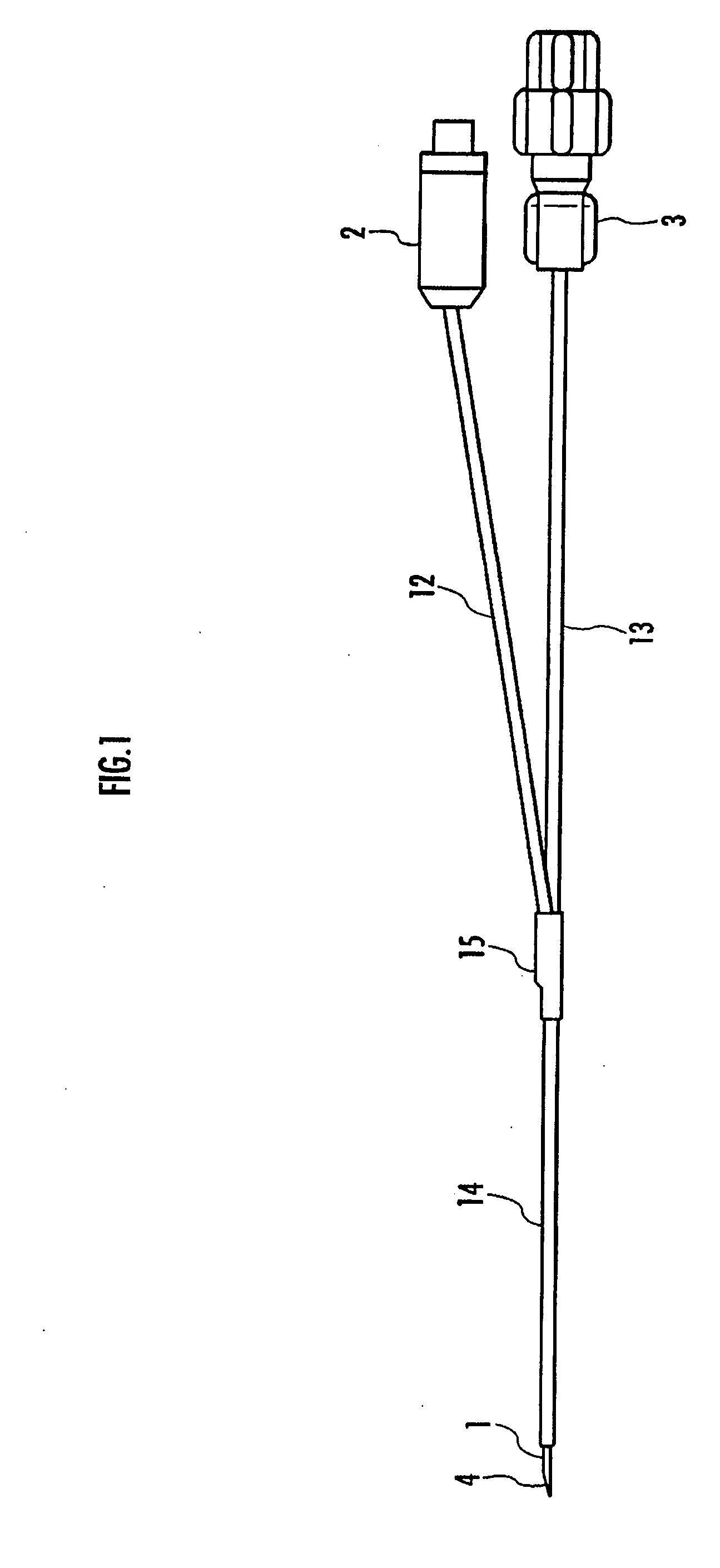
[0026]As shown in FIG. 1, the needle electrode device includes a needle electrode 1 to be pierced into an affected area of a living body, a first connector 2, for a connection between a feeder line and a signal line, and a second connector 3 for injecting a drug solution. The first connector 2 connects to a high frequency power source and temperature measurement means, which are not shown. The second connector 3 connects to drug solution injection means, which is not shown.

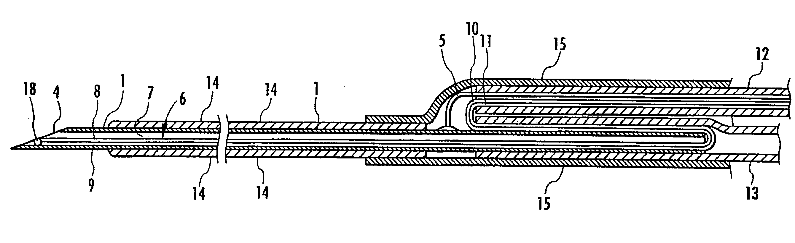
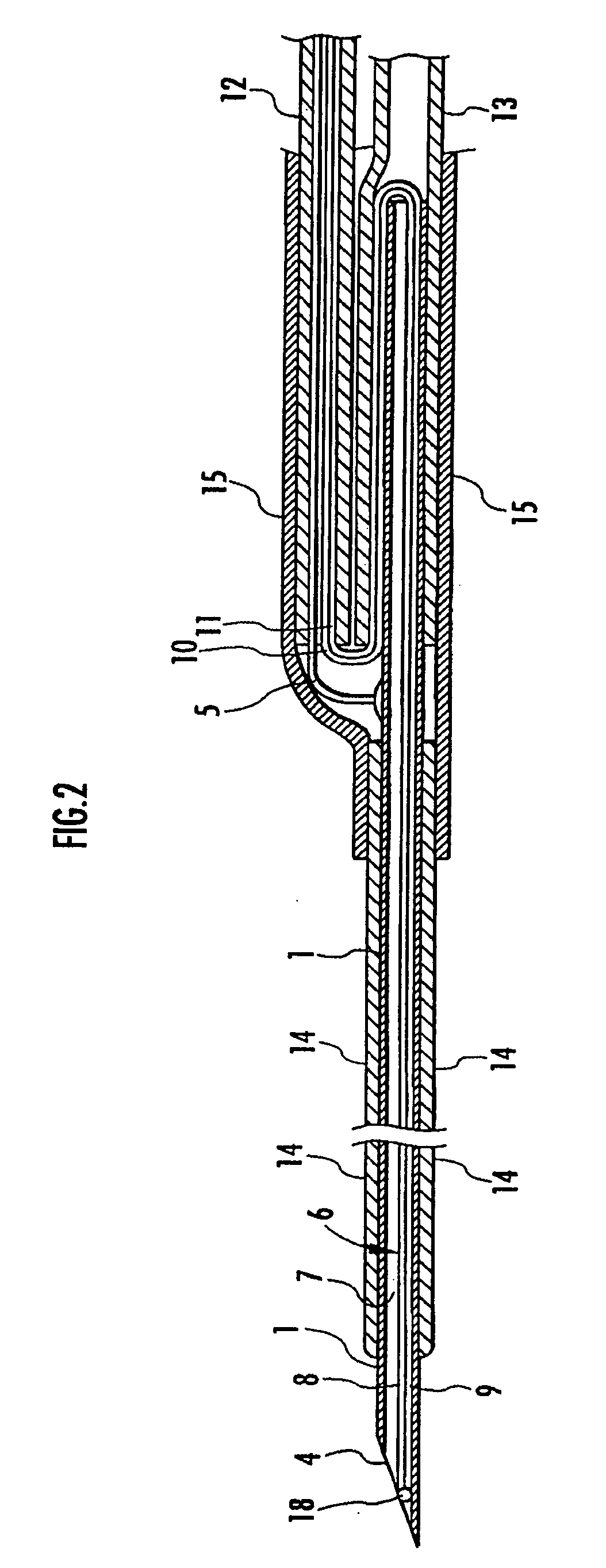
[0027]Describing the needle electrode device according to the first embodiment more specifically, as shown in FIG. 2, the needle electrode 1 is formed into a hollow stainless or other metal component having electrical conductivity and the tip of the needle electrode 1 is sharply formed with a beveled edge relative to the axis line of the needle electrode 1 as a blade surface 4.

[0028]Furthermore, a feeder line 5 is electrically connected to the outer surface of the bottom of the needle electrode 1 with solder and ...

second embodiment

[0035]Moreover, in the second embodiment, the thermocouple 6 is contained between the needle electrode 1 and the first coating material 14 as shown in FIG. 6. Therefore, the thermocouple 6 is firmly supported by the first coating material 14 and it is possible to reliably prevent an inadvertent movement or misalignment of the thermocouple 6 though the tip of the thermocouple 6 is bonded to only a part of the outer surface of the needle electrode 1.

INDUSTRIAL APPLICABILITY

[0036]As described hereinabove, according to the present invention, the needle electrode is provided with the thermocouple in a compact form and the thermocouple can detect a temperature very accurately. Therefore, the present invention can be preferably used as a needle electrode device for thermally coagulating an affected tissue by supplying radiofrequency current to a needle electrode pierced into the affected area of a living body.


PUM


Abstract

A thermocouple (6) is provided for detecting a temperature of the tip of a needle electrode (1). The thermocouple (6) includes a tip connecting portion (18) where the tips of a pair of coated wires (8, 9) are electrically connected to each other and a tip coated portion where the tip connecting portion (18) is coated with polyolefin synthetic resin. The tip coated portion is bonded and fixed to the needle electrode (1). They provide a needle electrode device for medical application capable of being compact with the needle electrode provided with the thermocouple and of detecting a temperature using the thermocouple with high accuracy.

Description

TECHNICAL FIELD[0001]The present invention relates to a needle electrode device for medical application that is pierced into an affected area to perform therapeutic thermocoagulation by radiofrequency current.BACKGROUND ART[0002]Conventionally, there is already known a needle electrode device for thermally coagulate affected tissue by supplying radiofrequency current to a needle electrode pierced into the affected area of a living body (for example, refer to Japanese Unexamined PCT Publication No. 2002-532186).[0003]This type of needle electrode device has a needle electrode whose tip is sharply formed and the needle electrode is supplied with radiofrequency current via a lead wire electrically connected to the needle electrode. With the tip placed on the affected area, the needle electrode heats the area around the tip of the needle electrode by the supplied radiofrequency current to thermally coagulate the affected tissue.[0004]If the needle electrode generates the heat insufficie...

Claims


Application Information

Patent Timeline
IPC IPC(8): A61B18/18
CPCA61B2018/00821A61B18/1477
Inventor KOBAYASHI, SUSUMUYAMADA, HIDEHIKOIIDA, NAOYUKI
Owner KK TOPCON
Why Eureka
Try Eureka