Multi-Fuel Storage System And Method Of Storing Fuel In A Multi-Fuel Storage System

a multi-fuel storage and storage system technology, applied in the direction of gaseous fuels, fuel cells, gas generation devices, etc., can solve the problems of difficult to find space to store an adequate amount of fuel, bulky storage tanks, and difficult to store hydrogen as compressed gas. , to achieve the effect of reducing time, reducing energy consumption, and reducing tim

Active Publication Date: 2009-03-12
WESTPORT FUEL SYST CANADA INC
View PDF6 Cites 10 Cited by
  • Summary
  • Abstract
  • Description
  • Claims
  • Application Information

AI Technical Summary

Benefits of technology

[0020]The method can further comprise pre-cooling the second gaseous fuel prior to introducing the second gaseous fuel into the second thermally insulated space. The second gaseous fuel that is supplied to fill the second thermally insulated space can be delivered at a temperature that is close to ambient temperature. The first fuel that is supplied to fill the first thermally insulated space can be supplied in liquefied form and already at the desired storage temperature. According to the method, the second gaseous fuel need not be pre-cooled from ambient temperature to storage temperature, but any pre-cooling that is done can reduce the time required to cool the second fuel to storage temperature and reduce the time needed to fill the second thermally insulated space with second gaseous fuel with the desired mass density. In a preferred method, the first gaseous fuel and the second gaseous fuel can be directed to a heat exchanger in which the first gaseous fuel can be used to pre-cool the second gaseous fuel.
[0021]The method can further comprise reforming the first gaseous fuel to produce the second gaseous fuel. The adva

Problems solved by technology

Storage of hydrogen as a compressed gas can be a problem because of the much larger volume that is required to store a suitable amount of fuel, compared to a conventional liquid fuel with the same amount of energy.
Storage density of gaseous hydrogen can be increased by storing it at higher pressures, but this requires that the fuel tanks be built to withstand such higher pressures and this makes the storage tanks bulky, heavy, and expensive.
Compared to conventional liquid fuels, the storage volume required to store hydrogen in the gaseous phase is higher, even at pressures as high as 70 MPa (about 10,150 psia), and so, for a vehicular application, it can be difficult to find space to store an adequate amount of fuel to give the vehicle a practical range between refueling.
However, liquefying hydrogen is energy intensive and storage of hydrogen as a liquefied gas can also be problematic because of the very low temperatures needed to keep hydrogen in liquefied form, which, depending upon the storage pressure can be at least as low as 20 degrees Kelvin (about −253 degrees Celsius or about −424 degrees Fahrenheit).
Because of the very low temperature for storing liquefied hydrogen, there are higher temperature gradients between the storage space and the ambient environment and even a small amount of heat leak into a cryogenic storage container can result in vaporization of some of the liquefied gas.
When liquefied gas in a storage vessel is vaporized, if fuel is not consumed quickly enough to reduce the vapor pressure, to maintain vapor pressure below the designed pressure limits of the storage vessel it may be necessary to vent vapor from the storage vessel, which results in fuel being wasted and hydrogen being releas

Method used


Image

  • Multi-Fuel Storage System And Method Of Storing Fuel In A Multi-Fuel Storage System
  • Multi-Fuel Storage System And Method Of Storing Fuel In A Multi-Fuel Storage System
  • Multi-Fuel Storage System And Method Of Storing Fuel In A Multi-Fuel Storage System

Examples


Embodiment Construction

)

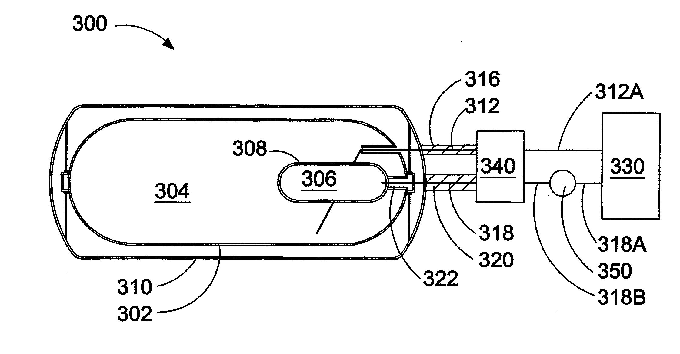
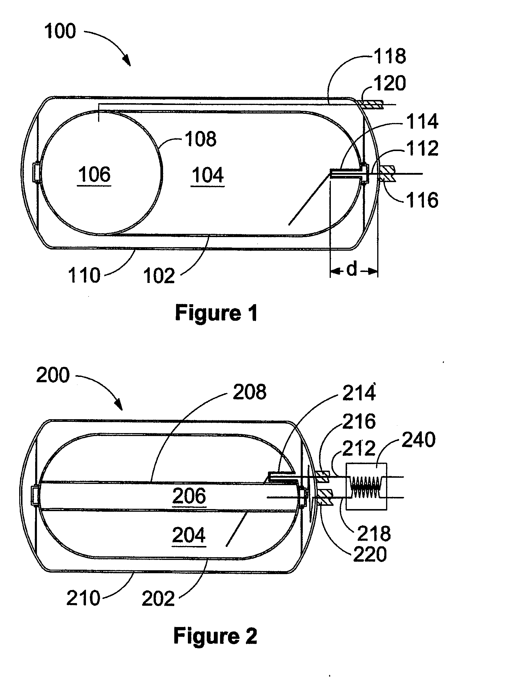
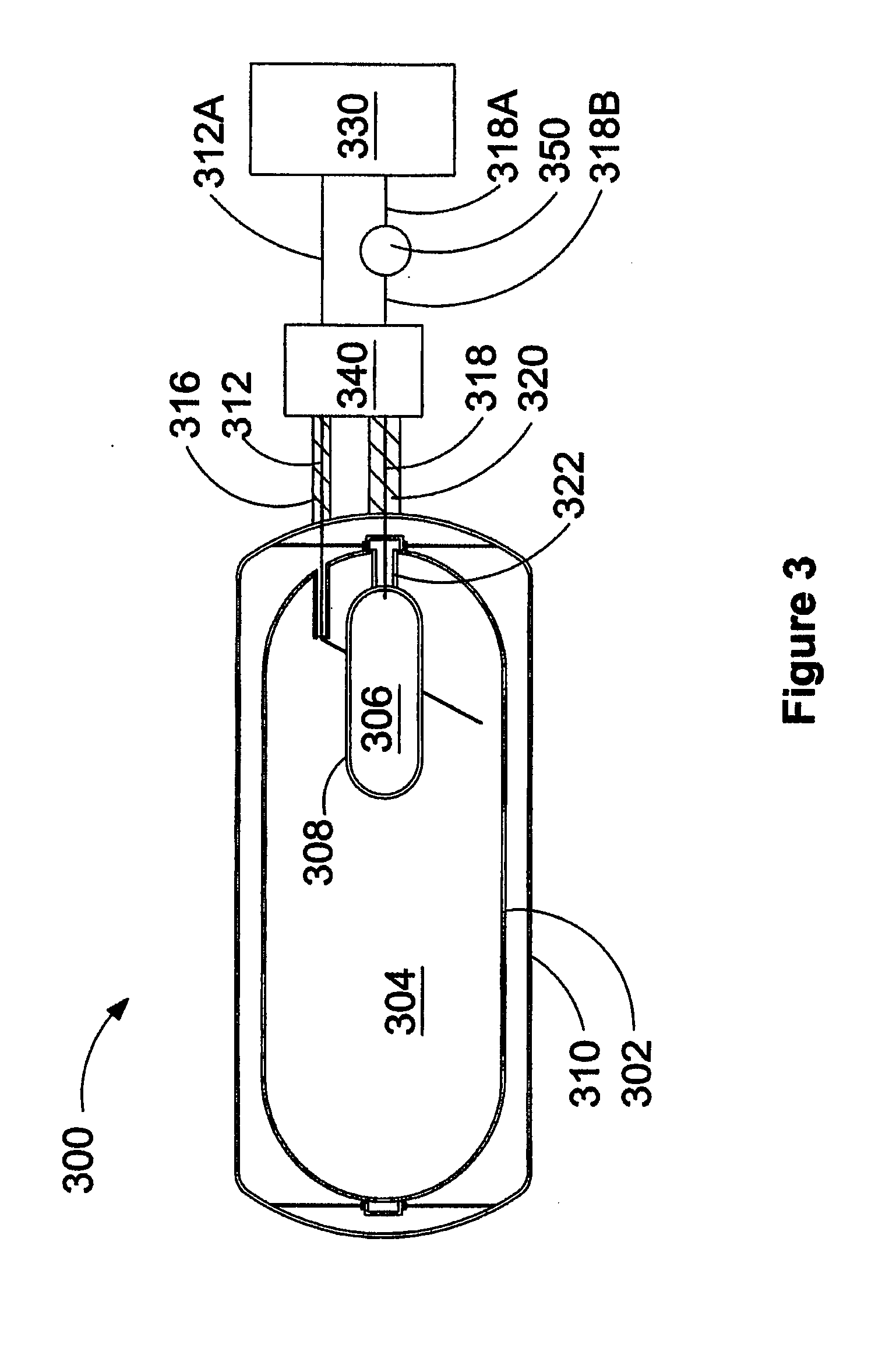
[0026]FIG. 1 is a schematic drawing of apparatus 100 for separately storing and delivering a first gaseous fuel and a second gaseous fuel. Apparatus 100 comprises first vessel 102, which defines first thermally insulated space 104 in which the first gaseous fuel can be stored in liquefied form. Second thermally insulated space 106, which can hold the second gaseous fuel, is disposed within first vessel 102. Second thermally insulated space 106 is separated from first thermally insulated space 104 by thermally conductive barrier 108. The second gaseous fuel liquefies at a lower temperature than the first gaseous fuel so that the second gaseous fuel can be stored within second thermally insulated space 106 in a gaseous form. While both first and second thermally insulated spaces 104 and 106, are respectively thermally insulated from the ambient temperature outside outer shell 110, thermally conductive barrier 108 is a partition wall that divides the space inside vessel 102 into first...


PUM


Abstract

Reduced emissions of nitrogen oxides can be achieved if engines are fuelled with mixtures of gaseous fuels such as hydrogen and natural gas. Storing the gaseous fuels separately is desirable so that the fuel mixture ratio can be changed responsive to engine operating conditions. The present apparatus increases the storage density of gaseous fuels such as hydrogen by storing them in gaseous form at high pressures and at sub-ambient temperatures. A first thermally insulated space for holding a first gaseous fuel in a liquefied form is separated from a second thermally insulated space for holding a second gaseous fuel by a thermally conductive fluid barrier. The second gaseous fuel liquefies at a lower temperature than the first gaseous fuel such that the second gaseous fuel can be stored within the second thermally insulated space in a gaseous form at a sub-ambient temperature.

Description

CROSS-REFERENCE TO RELATED APPLICATION(S)[0001]This application is a continuation of International Application No. PCT / CA2007 / 000430, having an international filing date of Mar. 13, 2007, entitled “Multi-Fuel Storage System And Method Of Storing Fuel In A Multi-Fuel Storage System”. The '430 international application claimed priority benefits, in turn, from Canadian Patent Application No. 2,539,232 filed Mar. 22, 2006. The '430 international application is hereby incorporated by reference herein in its entirety.FIELD OF THE INVENTION[0002]The present invention relates to a multi-fuel storage system and a method of storing fuel in a multi-fuel storage system. More particularly, the invention relates to an apparatus and method for separately storing two gaseous fuels with a higher density than the same fuels when both are stored as compressed gases.BACKGROUND OF THE INVENTION[0003]There can be advantages gained by fuelling an engine with two different gaseous fuels and having the abil...

Claims


Application Information

Patent Timeline
IPC IPC(8): B01J8/00F17B1/00
CPCB60K15/03006F17C2223/0123F17C2201/0147Y02E60/321F17C2223/036F17C2227/0157F17C2227/0393F17C2260/044F17C2265/015F17C2265/025F17C2270/0168F17C2201/0109F17C2205/0149F17C2205/0358F17C2221/012F17C2221/033F17C5/04Y02E60/32
Inventor MUNSHI, SANDEEPGRAM, ANKER
Owner WESTPORT FUEL SYST CANADA INC
Why Eureka
Try Eureka