Methods, Wires, and Apparatus for Slicing Hard Materials

a technology of wires and hard materials, applied in the direction of soldering equipment, metal sawing tool making, other chemical processes, etc., can solve the problems of low efficiency of consumable abrasives, low and loss of kerfs and cutting efficiency of id saws

Active Publication Date: 2009-03-12
UNIVERSITY OF SOUTH CAROLINA
View PDF1 Cites 54 Cited by
  • Summary
  • Abstract
  • Description
  • Claims
  • Application Information

AI Technical Summary

Benefits of technology

[0016]A method of slicing a workpiece to create wafers is also generally provided. According to this method, a workpiece (or more than one workpiece) can be encased within a holder. The holder is rotated to create a tangential movement of the holder about a center axis. Then, the rotating holder is contacted with an abrasive wire moving in a direction substantially opposite to the tangential movement of the holder. The abrasive wire can be moved toward the center axis of the rotating holder as the abrasive wire cuts deeper into the holder to cut through entire workpiece.

Problems solved by technology

However, kerf loss and cutting efficiency of ID saws are not suitable for extremely hard materials such as SiC.
This technique is often quite slow.
Also, the efficiency of the consumable abrasive slurry is low resulting in high cost of operation.
However, the surface quality of the produced wafers is poor.
However, for cutting extremely hard, brittle materials, such as a silicon carbide or sapphire, wire fixed with a so-called super-abrasive such as diamond, is required.
However, the manufacturing cost of the electrodeposition abrasive wire is high since it takes a long time to bond the abrasives by electrodeposition.
Further, the abrasive wire cannot be made long enough for large multi-wire cutting machines, which require lengths of more than 50 km.
However, the resin bonded abrasive wire does not produce satisfactory results with respect to the abrasion resistance, mechanical strength, heat resistance, and cutting ability.

Method used


Image

  • Methods, Wires, and Apparatus for Slicing Hard Materials
  • Methods, Wires, and Apparatus for Slicing Hard Materials
  • Methods, Wires, and Apparatus for Slicing Hard Materials

Examples


example

Forming a Composite Super-Abrasive Wore

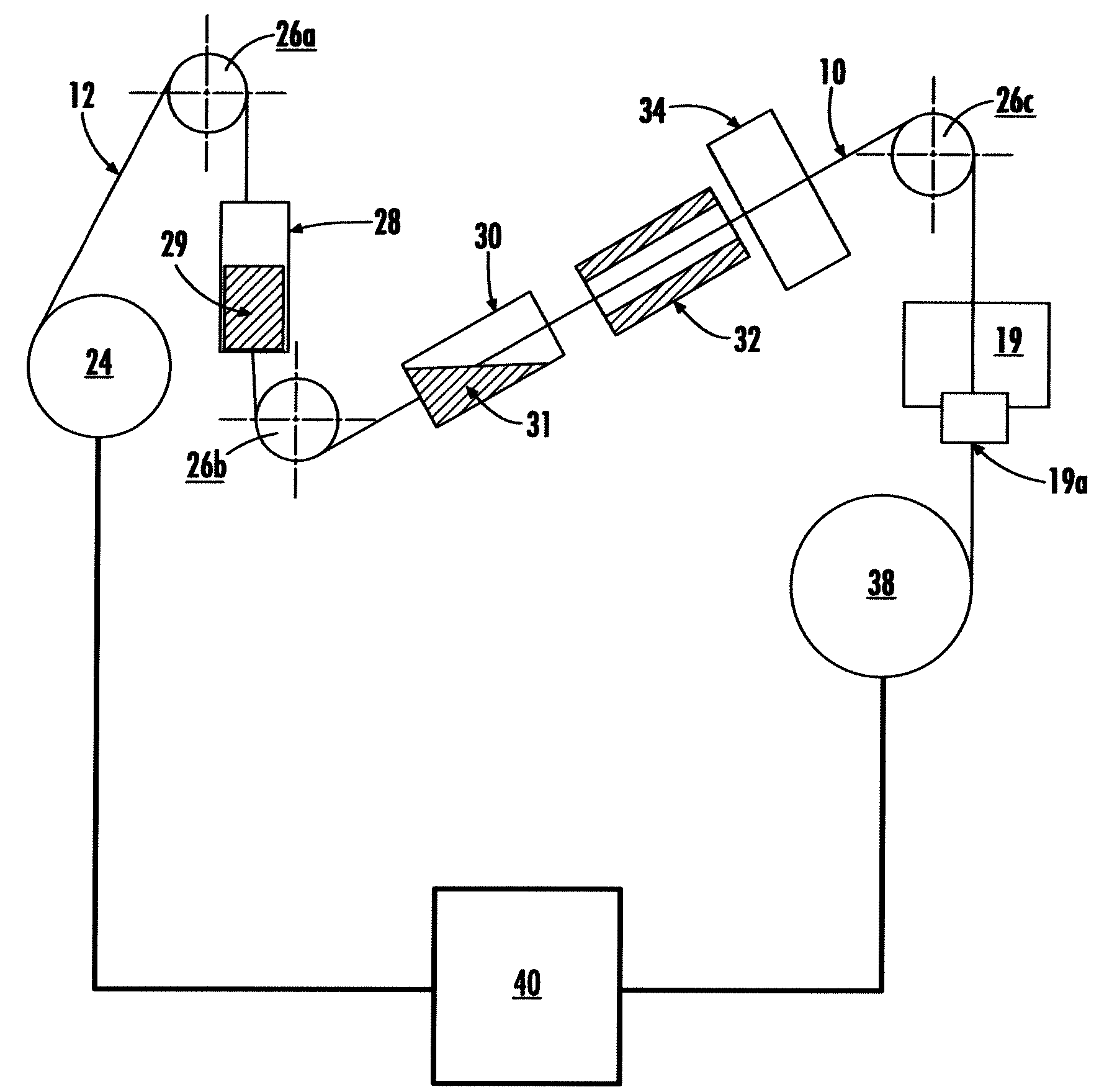
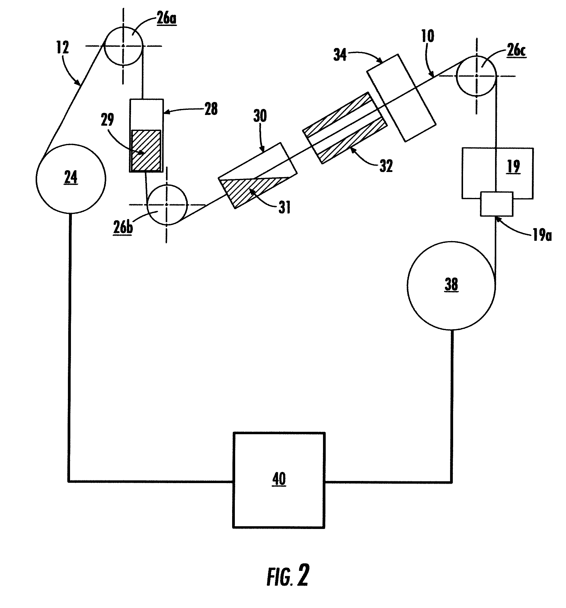
[0070]The following is a description of the composite super-abrasive wire formed by an apparatus as shown in FIG. 2:

[0071]A wire core metal wire having a diameter of about 230 microns (tin coated or high tensile steel wire) was etched by passing through an etching bath of an acid containing an aggressive liquid flux (N-3 by LA-CO Industries, Inc. Elk Grove, Ill.) maintained at room temperature. As the wire exited the etching bath, it was wound on a “take-off” spool. The etched wire was then introduced into the liquid flux applying chamber so that the wire was covered by the liquid flux (water soluble paste flux sold under the designation H-205 by Oatey Co., Cleveland, Ohio). The wire was then passed through a powder chamber so that the wire was covered by the mixture, which includes the powdered solder alloy (96.5% tin and about 3.5% silver, mesh −400 / +500; Amtech, Inc., Branford, Conn.), the powdered flux material (Rosin Powder, Todd & Moore s...


PUM

PropertyMeasurementUnit
temperatureaaaaaaaaaa
lengthsaaaaaaaaaa
roughnessaaaaaaaaaa

Abstract

Methods, wires, and apparatus for use in cutting (e.g., slicing) hard, brittle materials is provided. The wire can be a super-abrasive wire that includes a wire core and super-abrasive particles bonded to the wire core via a metal bonding layer. This wire, or another type of wire, can be used to slice workpieces useful for producing wafers. The workpieces can be aligned within a holder to produce wafers using the device and methods presently provided. The holder rotates about its central axis, which translates to workpieces moving in orbit around this axis. A single abrasive wire, or multiple turns of wire stretched tightly between wire guides, is then contacted with the rotating holder to slice the workpieces.

Description

PRIORITY INFORMATION[0001]The present application claims priority to Provisional Patent Application Ser. No. 60 / 967,560 filed on Sep. 5, 2007, the disclosure of which is incorporated by reference herein.GOVERNMENT SUPPORT CLAUSE[0002]The present invention was developed with funding from the Office of Naval Research under Grant N00014-01-1-0282. Therefore, the government retains certain rights in this invention.BACKGROUND OF THE INVENTION[0003]The wafering process is necessary in the semiconductor industry because semiconductor devices are fabricated on flat surfaces. Bulk semiconductor material such as Si, SiC, and GaAs are grown as long cylindrical crystals. In order to minimize device size and maximize the surface area available for device fabrication, these cylindrical ingots must be sliced into thin wafers.[0004]Several techniques have been employed to slice semiconductor ingots into wafers. Rotary ID saws are common for softer materials. ID saws use an abrasive impregnated disc...

Claims


Application Information

Patent Timeline
Patent Type & Authority Applications(United States)
IPC IPC(8): B28D1/08C09K3/14B23K1/19B24D3/10
CPCB05C19/04B24B27/0633B28D1/124B05C9/14B05C9/12B05C3/125B23D65/00B23D61/185B28D5/045C23C24/106B05C9/10B28D5/0082
Inventor SUDARSHAN, TANGALIAGAFONOV, IGORKENNEDY, ROBERT
Owner UNIVERSITY OF SOUTH CAROLINA
Why Eureka
Try Eureka