
Buck-boost switching regulator

a switching regulator and buck-boost technology, applied in the direction of automatic control, process and machine control, instruments, etc., can solve the problems of buck-boost operation difficulty, need a more complex pwm modulator, and conventional average current mode devices suffer from various implementation challenges, so as to achieve superior efficiency, reduce ripple current value, and improve light load efficiency

Inactive Publication Date: 2009-03-12
PANASONIC SEMICON SOLUTIONS CO LTD
View PDF41 Cites 45 Cited by
  • Summary
  • Abstract
  • Description
  • Claims
  • Application Information

AI Technical Summary

Benefits of technology

[0012]It is another objective of the present invention to provide a buck-boost switching regulator providing for automatic transition between DCM and CCM and the use of current mode and supply voltage feedforward control so as to provide rejection of both load current and supply voltage changes in the output voltage as well as to minimize changes in transient response time as a function of load current operating point.
[0013]It is yet another objective of the present invention to provide a buck-boost switching regulator that provides for fixed frequency operation in both the DCM and CCM modes, so as to eliminate the adverse affects of unwanted frequency spectrum signals associated with BURST mode operation.
[0017]One advantage of the switching regulator of the present invention is that it provides for fixed frequency operation in the discontinuous inductor current mode “DCM” at small values of load current, which provides superior light load efficiency, and for operation in the continuous inductor current mode “CCM” at large values of load current for the purpose of reducing the value of ripple current in the inductor and output capacitor (and therefore the ripple voltage at the voltage output) as well as providing superior efficiency at heavy loads.
[0018]Yet another advantage is realization of automatic transition between DCM and CCM. Furthermore, the use of current mode control and supply voltage feedforward provides rejection of both load current and input voltage changes in the output voltage as well as minimizes changes in transient response time as a function of load current operating point, and eliminates the need for slope compensation and its added complexity. Average current mode is also much more tolerant of noise on the current signal than instantaneous current control.

Problems solved by technology

However, the conventional “peak” current mode requires wide bandwidth current measurement, is very sensitive to noise on the current waveform, requires slope compensation in the PWM modulator to avoid instability when operating over a wide range of switch duty cycles and is difficult to configure for buck-boost operation.
However, conventional average current mode devices suffer from various implementation challenges.
Specifically, such devices require continuous inductor current measurement, not the intermittent switch currents; require supply voltage feed forward to maintain constant PWM gain at varying supply voltage; and need a more complex PWM modulator, especially for buck-boost operation.
However, it can not easily provide negative polarity inductor current when needed to program a rapid decrease in the output voltage value.

Method used


Image

  • Buck-boost switching regulator
  • Buck-boost switching regulator
  • Buck-boost switching regulator

Examples


Embodiment Construction

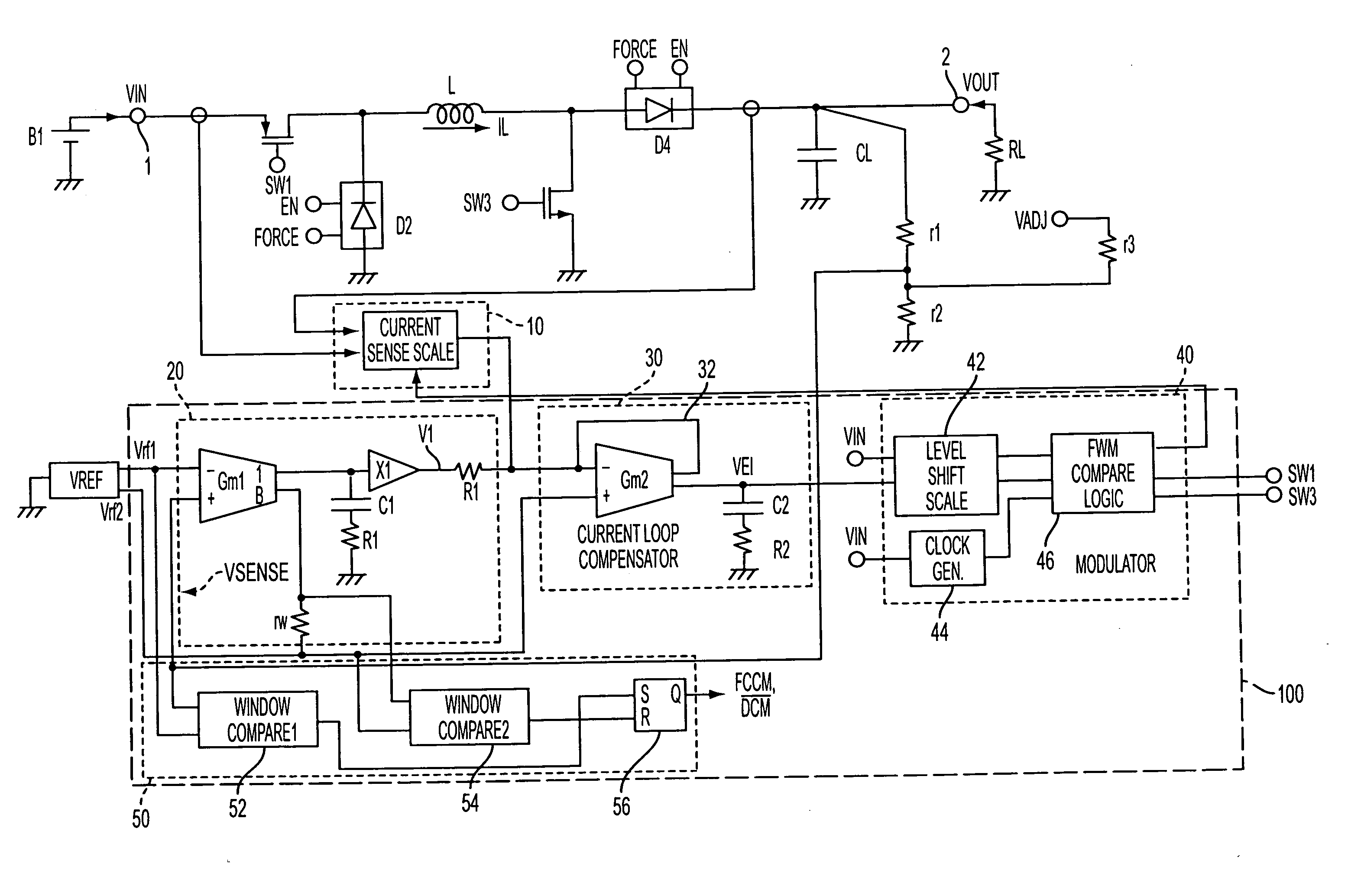
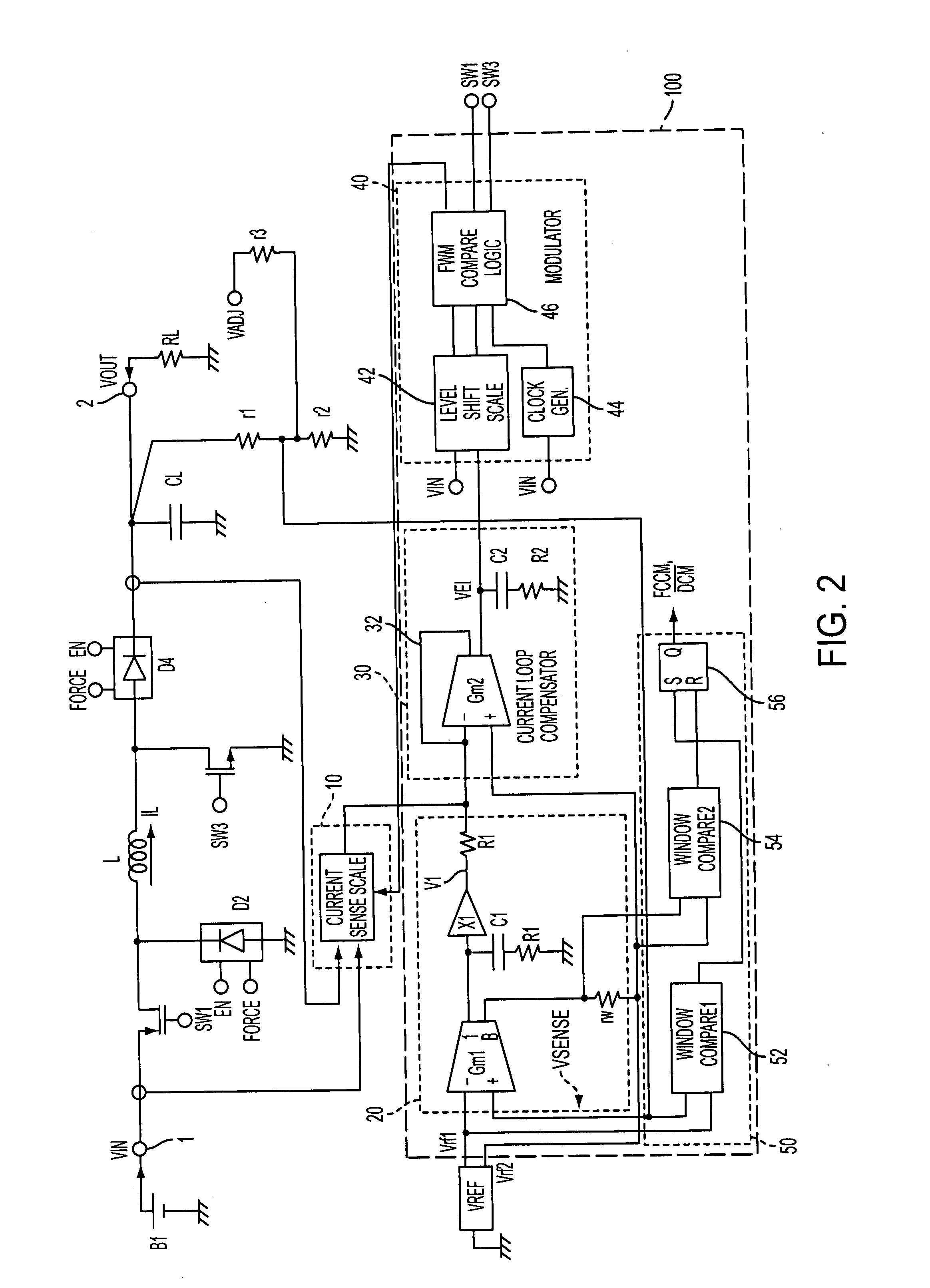
[0024]An exemplary configuration of the switching regulator in accordance with the present invention is shown in FIG. 2. The switching regulator in the given embodiment utilizes average current control mode and employs an input voltage (VIN) feed-forward configuration for good supply voltage rejection. The switching regulator also operates at fixed switching frequency in both continuous and discontinuous inductor current modes (CCM and DCM, respectively), and is capable of both sourcing and sinking current in the output capacitor and load for fast output voltage programming and load change transient response. All current sensing and frequency response determining components as well as the switches and diodes may be integrated in an IC to save space and cost.

[0025]As noted above, average current mode operation is utilized in the present invention. The inductor current IL is measured, its value is time averaged and the averaged current is used for controlling the switches of the switc...


PUM


Abstract

A buck-boost switching regulator which includes a first switch, a first diode, an inductor, a second switch, a second diode, and a controller for controlling the first switch and the second switch, the controller being configured to receive a current signal indicative of a inductor current flowing in the inductor, and generating a signal indicative of an average current flowing in the inductor, the average current being utilized to control the first switch and the second switch, wherein the controller includes a first compensator circuit for outputting a voltage error signal, a second compensator circuit for outputting a current error signal and a modulator circuit to output a first control signal to control the first switch and a second control switch to control the second switch.

Description

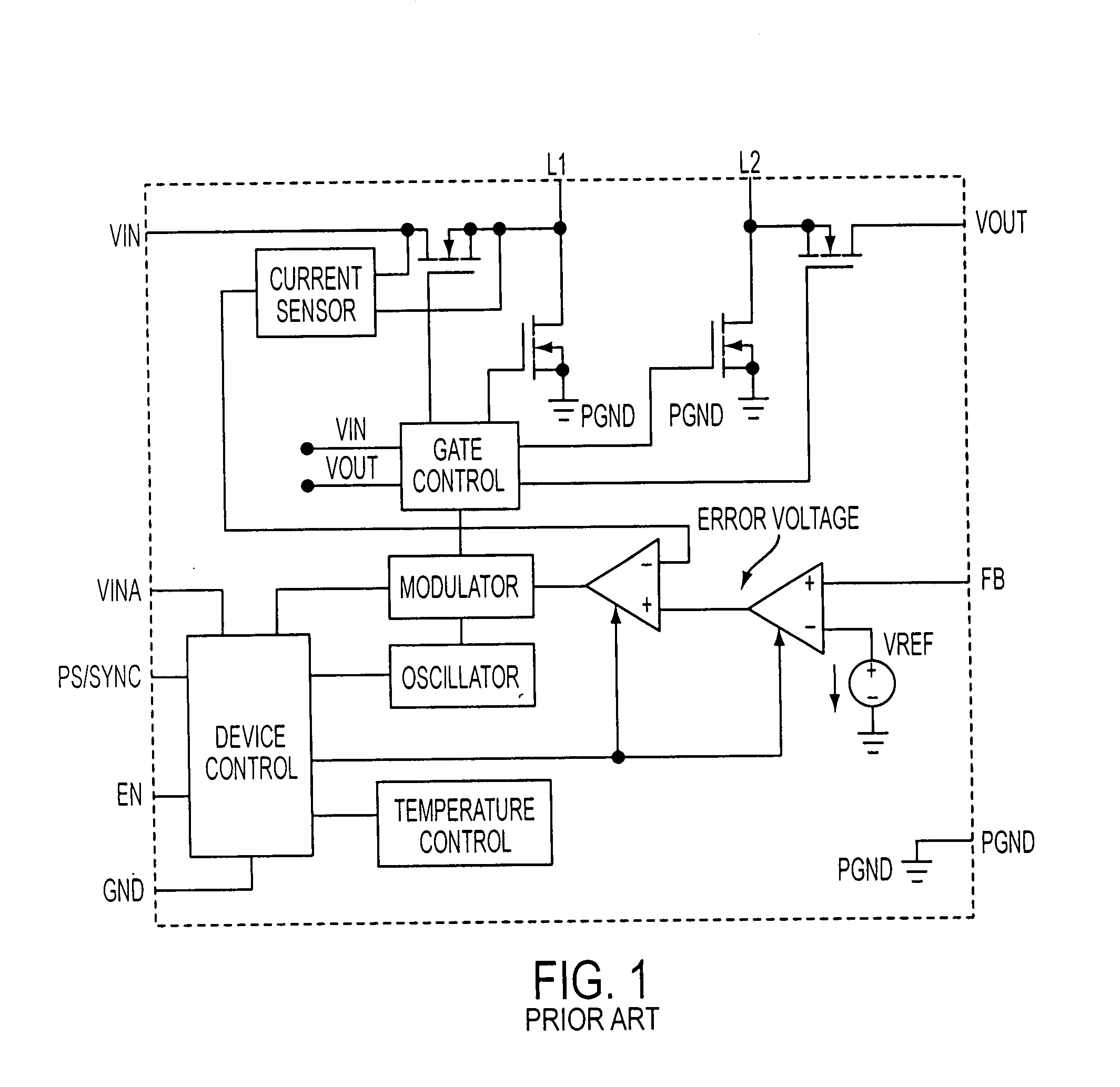
RELATED APPLICATIONS[0001]U.S. Pat. No. 7,199,636 (filed on Mar. 31, 2005) which is entitled “Active Diode” and U.S. Patent Application Publication 20060044853 (filed on Aug. 19, 2005) which is entitled “Performance controller for a step down current mode switching regulator” are herein incorporated by reference.BACKGROUND OF THE INVENTION[0002]1. Field Of The Invention[0003]This invention relates to an inductor based switching regulator in which the output voltage can be less than, equal to, or greater than the input supply voltage. In particular, this invention relates to a buck-boost (step down-step up) type switching regulator which exhibits better performance than those of the prior art.[0004]2. Background Of The Related Art[0005]Most prior art buck-boost regulators utilize voltage mode control where the inductor current is not measured at all or at least not utilized in the control process. A typical configuration of a conventional buck-boost switching regulator is shown in FI...

Claims


Application Information

Patent Timeline
IPC IPC(8): G05F1/00H02M3/158
CPCH02M3/1582
Inventor OSWALD, RICHARDYAMAMOTO, TAMOTSURYU, TAKASHI
Owner PANASONIC SEMICON SOLUTIONS CO LTD
Learn More