

Film deposition apparatus and method of film deposition
a film deposition apparatus and film technology, applied in the direction of electrolysis components, vacuum evaporation coatings, coatings, etc., can solve the problems of affecting the smoothness of the surface, and affecting the adhesion of the film
- Summary
- Abstract
- Description
- Claims
- Application Information
AI Technical Summary
Benefits of technology
Problems solved by technology
Method used
Image

Examples
first embodiment
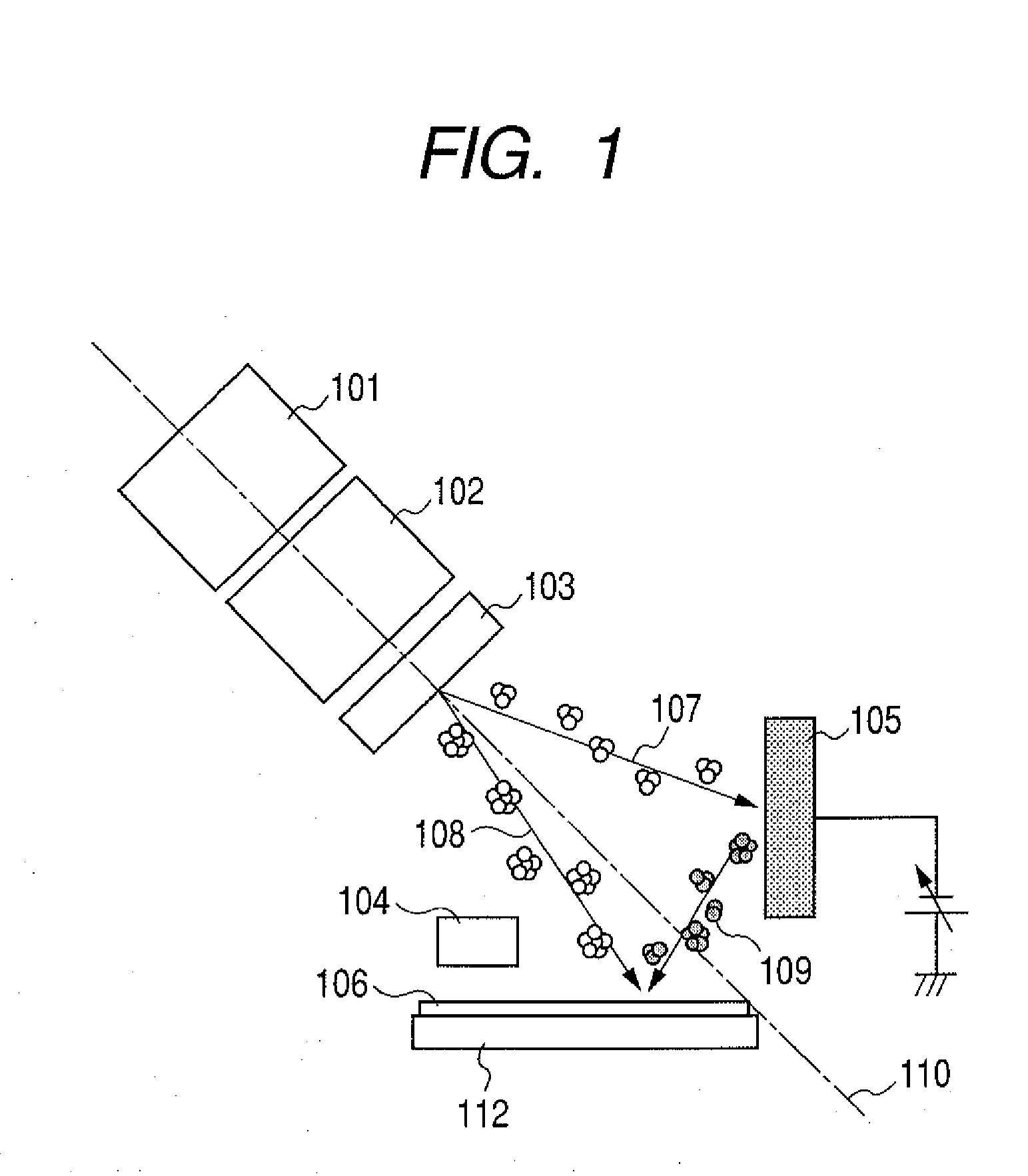
[0020]A film deposition apparatus of the first embodiment has, as shown in FIG. 1, ion beam irradiation unit composed of a gas cluster ion source 101, a set of electrodes for extraction, acceleration and focusing 102, and mass separation unit 103.
[0021]It also has a neutralizer104, a target 105 provided with a bias voltage impression mechanism and a substrate 106. The set of electrodes 102 extracts gas cluster ions from the gas cluster ion source 101, and accelerates the ions to a predetermined direction. Herein, “gas cluster ion” is obtained by ionizing a cluster, which is generated by ejecting high pressure gas into vacuum through a nozzle and cooling a gas by thermal expansion, by electron impact, etc. The “gas cluster ion source” is an apparatus in which gas cluster ions are generated.
[0022]The mass separation unit 103 deflects the trajectories of the gas cluster ions according to the masses of the ions by imparting a predetermined electric and magnetic fields to the gas cluster...
second embodiment
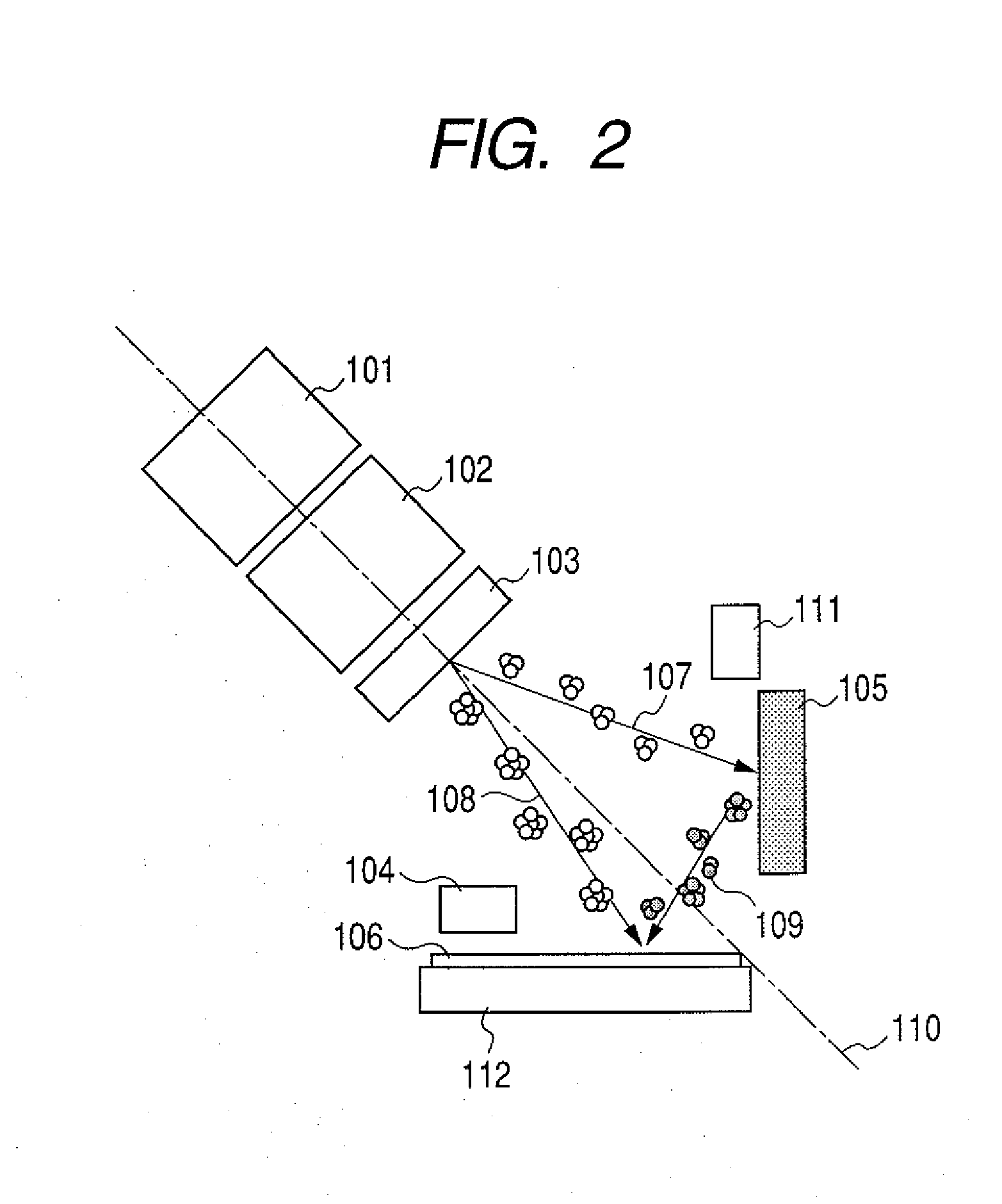
[0038]The present invention is not limited to the above-mentioned embodiment, and various changes and modifications are possible. Hereinafter, this will be described referring to FIG. 2.
[0039]A film deposition apparatus of is FIG. 2 is a modified system produced by a partial change in configuration of the film deposition apparatus of FIG. 1, and has different points that a neutralizer 111 is installed also in the vicinity of a target 105, not only in the vicinity of a substrate 106, and that a bias is not impressed on the target 105. By thus installing the neutralizers 104, 111 to supply electrons, the charge-up of the target 105 and the substrate 106 are prevented. The configuration of FIG. 2 is one in which an insulating material is sputtered instead of a conductive material.
[0040]A more specific example will be described hereinafter. In the embodiment, oxygen (O2) pressurized at 0.8 MPa was used as a source gas of the gas cluster ion source 101, and adiabatically expanded into va...
third embodiment
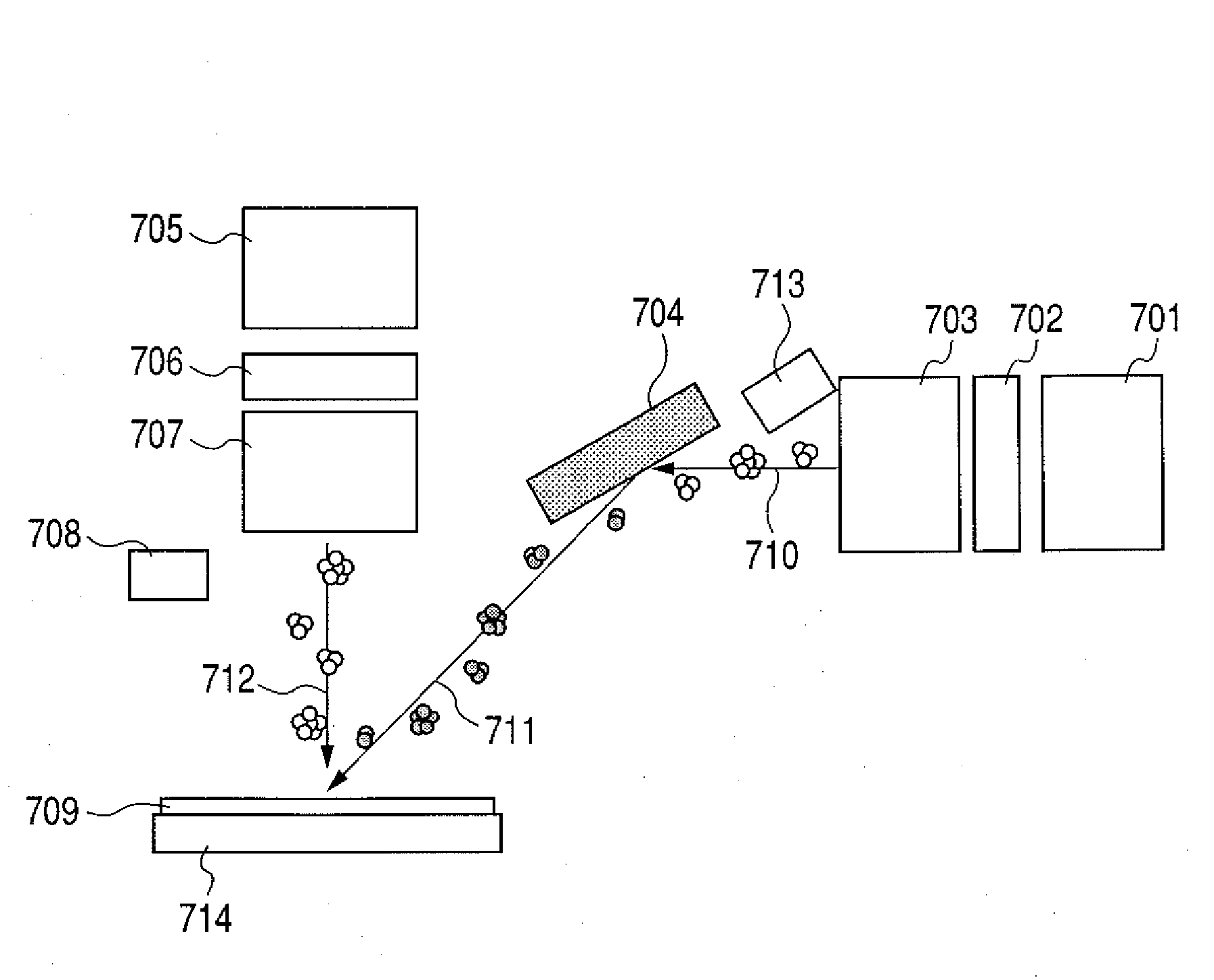
[0044]A film deposition apparatus of the present invention may be one shown in FIG. 3. The film deposition apparatus of FIG. 3 has ion beam irradiation unit composed of a gas cluster ion source 301, a set of electrodes for extraction, acceleration and focusing 302 and mass separating unit 303, and a neutralizer 304, as the apparatus of the first embodiment (see FIG. 1). It also has a target 305 equipped with a bias voltage impressing mechanism, a substrate 306 and holding unit 312 of the substrate 306. The different point from the configuration of the apparatus of FIG. 1 is that a fan-shaped permanent magnet 303 to form a fan-shaped beam path is installed as mass separation unit in place of the transverse field mass separator 103. The fan-shaped permanent magnet enlarges the apparatus volume, but has a simple and easily handleable structure. An example of the operation of the film deposition apparatus shown in FIG. 3 is as follows.
[0045]Gas cluster ions generated by the gas cluster ...
PUM
| Property | Measurement | Unit |
|---|---|---|
| Energy | aaaaa | aaaaa |
| Energy | aaaaa | aaaaa |
| Energy | aaaaa | aaaaa |
Abstract
Description
Claims
Application Information