Process for production of hydrogen from coal and other fossil fuels

a technology of coal and other fossil fuels, applied in the direction of combustible gas production, molten salt/metal gasification, sustainable manufacturing/processing, etc., can solve the problem of not being commercially viabl

Inactive Publication Date: 2009-03-19
BILLINGS CALVIN
View PDF8 Cites 20 Cited by
  • Summary
  • Abstract
  • Description
  • Claims
  • Application Information

AI Technical Summary

Benefits of technology

[0006]The present invention provides such an economical process. It is designed to supply clean, pollution free, hydrogen fuel to industry.

Problems solved by technology

If the syngas product is too expensive because the process and equipment are too elaborate then it will not be commercially viable.

Method used


Image

  • Process for production of hydrogen from coal and other fossil fuels
  • Process for production of hydrogen from coal and other fossil fuels
  • Process for production of hydrogen from coal and other fossil fuels

Examples


example

[0031]The following test illustrates the efficacy of the gasifier reactor to achieve a high degree of gasification of powdered high sulfur coal.

Test Results

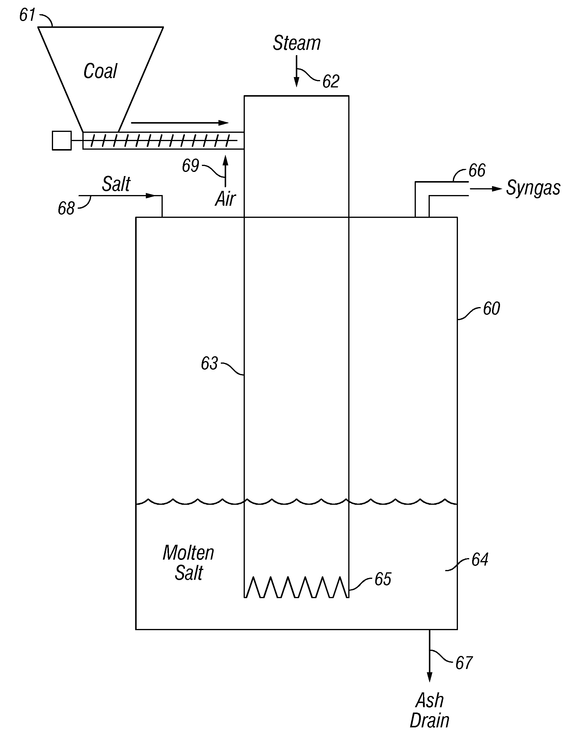
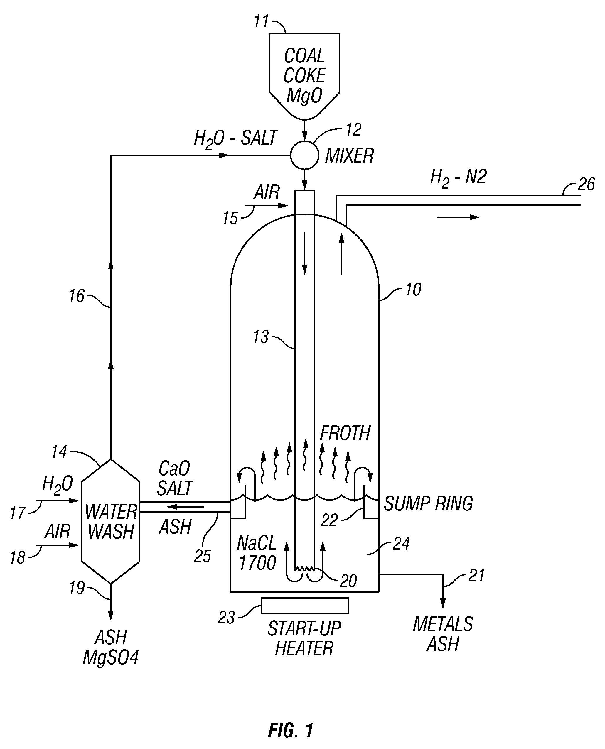
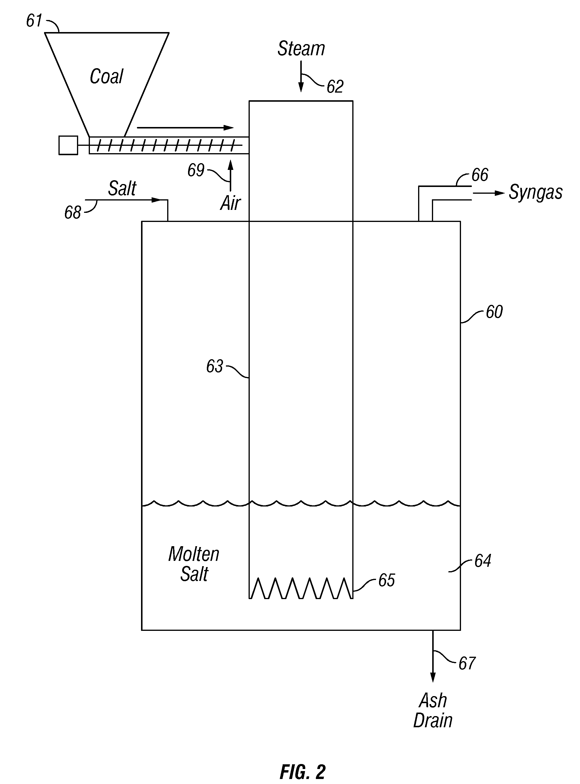
[0032]A prototype reaction vessel consisting of a 11″×29″ inconel vessel fitted with a 6.5″×36″ stainless steel pre-gasifier tube that is notched on the bottom and extends to 2″ off the bottom of the vessel was used for these tests. The vessel was filled with 40 pounds of NaCl salt and 2 pounds of olivine. It was heated by external electric heaters to 1750° F. and created a depth of 10 inches molten bath. A coal slurry ground to an average of 50 microns was mixed with two parts water to make a pumpable slurry. The slurry was pumped into the reactor at a flow rate of 3 ounces per minute. After ten minutes a sample of the outlet gas was collected and sent to a commercial lab for analysis. They reported:

H2—99.8%


PUM

PropertyMeasurementUnit
atmospheric pressureaaaaaaaaaa
depthaaaaaaaaaa
temperatureaaaaaaaaaa

Abstract

A process for converting coal or other fossil fuel to hydrogen by reacting the fossil fuel or coal with water in a molten salt reactor at elevated temperatures in the presence of a magnesium silicate wherein the magnesium silicate reacts with the CO2 produced in the reaction, thus removing it from the hydrogen gas product.

Description

CROSS REFERENCE TO RELATED APPLICATIONS[0001]This application claims the benefit of U.S. Provisional Application, No. 60 / 994,182, filed Sep. 18, 2007.FIELD OF THE INVENTION[0002]This invention relates to the production of hydrogen from coal and all other carbon containing fossil fuels. More specifically, this invention relates to a process for hydrogen production by the gasification of fossil fuels in a molten salt reactor followed by conversion of carbon monoxide to carbon dioxide and sequestration of the carbon dioxide with a magnesium silicate mineral.BACKGROUND[0003]There is a growing demand for hydrogen for use as a clean fuel for many applications as well as for fuel in fuel cells. Coal and other fossil fuels are an abundant source of carbon that when reacted with oxygen and water produces hydrogen. Thus, gasification of coal is a logical source for the production of hydrogen. The purpose for doing so is to remove the carbon from the fuel so that it can be sequestered and not ...

Claims


Application Information

Patent Timeline
Patent Type & Authority Applications(United States)
IPC IPC(8): C01B3/04
CPCC01B3/348C10J2300/1807C01B3/48C01B3/56C01B2203/0244C01B2203/0283C01B2203/04C01B2203/0475C01B2203/0833C01B2203/1241C01B2203/1604C01B2203/86C10J3/466C10J3/57C10J3/721C10J2200/15C10J2300/093C10J2300/094C10J2300/0943C10J2300/0956C10J2300/0973C10J2300/0983C01B3/382Y02E20/18Y02P30/00
Inventor BILLINGS, CALVIN
Owner BILLINGS CALVIN
Why Eureka
Try Eureka