Time multiplexed space switch

Inactive Publication Date: 2009-03-26
ZARRIS GEORGE
View PDF3 Cites 7 Cited by
  • Summary
  • Abstract
  • Description
  • Claims
  • Application Information

AI Technical Summary

Benefits of technology

[0007]Thus by producing multi-wavelength data pulse sequences a reduced number of optical gates is required. The gate could, for example, be based on semiconductor optical amplifier-based Mach-Zehnder interferometer or on any other technology or technique which can translate an input data pulse sequence into an output multi-wavelength data pulse sequence according to a multi-wavelength pulse sequence, which is also input to the gate.
[0008]Preferably the pulsed laser source is a quantum-dot mode-locked laser which can produce sub-picosecond high quality pulses. Preferably only one pulsed laser source is included although in some circumstances more than one pulsed sources may be provided, for example, when one pulsed source cannot produce all the required wavelengths. Preferably the plurality of wavelengths of pulsed radiation is provided by spectrally slicing the narrow pulse of the pulsed source with the use of spectral filters. Preferably such a filter is an arrayed waveguide grating. In some embodiments the spectral filters are followed by power splitters which split each wavelength pulse into a number of replicas. This allows the selection in the subsequent switch of more than one pulses of the same wavelength to produce a pulse sequence which includes more than one instances of the same wavelength pulse. In some other embodiments a larger number of wavelengths is provided to negate or reduce the requirement for splitters. In some embodiments optical variable attenuators are used in each or in some propagation paths in order to provide means of controlling the power of i

Problems solved by technology

This is because the implementation of time switching in the optical domain has been considered much more difficult.
Delaying channel tributaries in an optical medium, as would be required in the time-slot interchange part of an optical time multiplexed space switch, is conventionally considered problematic partly because there is no equivalent in optics of the Random Access Memory, which is typically employed by electronics to delay data channels

Method used


Image

  • Time multiplexed space switch
  • Time multiplexed space switch
  • Time multiplexed space switch

Examples


Embodiment Construction

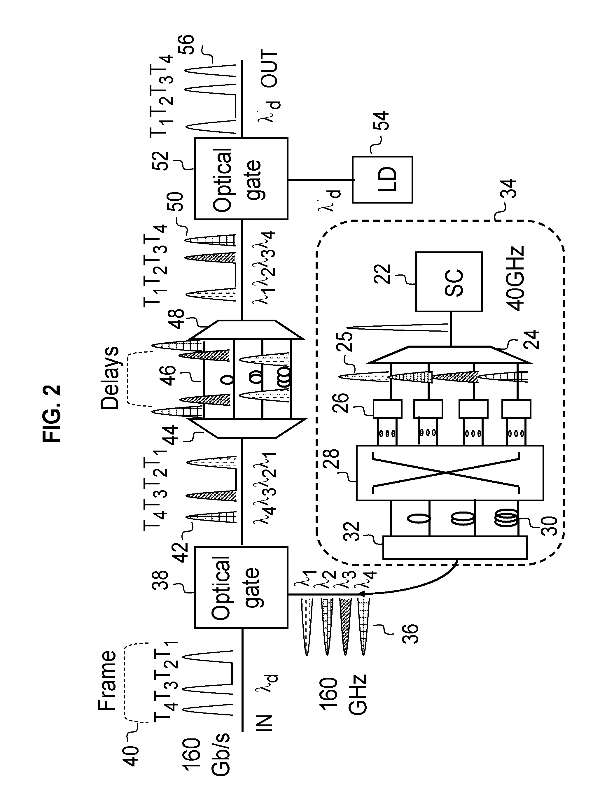
[0020]In FIG. 2, a laser source 22 of ultra-short pulse radiation (SC) produces a sequence of pulses of rate equal to the data tributary rate (say, 40 GHz), and is spectrally sliced, using a wavelength de-multiplexer 24, to produce a number of synchronous pulse sequences 25 (in this case, four) each at different wavelength. Subsequently, each pulse is split into a number of pulses of same wavelength using a power splitter 26. A space switch 28 selects a number of thus produced pulses and blocks and discards the pulses which are not needed. Each of the selected pulses is connected by the switch to a delay line 30 of appropriate time delay. In this example the four delay paths differ in delay by one bit period of the higher rate TDM data channel (160 Gb / s). A coupler 32 combines the delayed pulses. In this way, a multi-wavelength pulse sequence 36 is created of 160 GHz rate (4 times 40 GHz), which can be altered by re-configuring the space switch 28. Therefore, the system 34 is a puls...


PUM


Abstract

The present invention provides an optical time multiplexed space switch including a pulsed laser source, and means for producing from the laser source a plurality of wavelengths of pulsed radiation including means for providing permutable multi-wavelength pulse sequences from said multi-wavelength source and means for translating the input data pulses into the multi-wavelength pulse sequence. Each data pulse is subsequently guided through a wavelength selective structure, which may contain delay lines. In the case of time-slot interchange, the pulses are recombined in an interchanged sequence. In the case of tributary space switching different wavelength pulses are switched to generally different outputs and combine with pulses originating from different inputs. Alternatively, instead of or in addition to the means for providing permutable multi-wavelength pulse sequences from the pulsed source, means are provided for the permutation of the multi-wavelength data pulse sequence in reconfigurable wavelength selective structures.

Description

BACKGROUND[0001]The present invention relates to time division multiplexing of data channels and in particular to time division multiplexing and switching of bit-interleaved digital communication channels by optical techniques. The present invention is particularly applicable to communications switching systems in the core communication network.[0002]There is considerable interest today in ultra-high speed optical transmission. For example, 100 Gigabit per second Ethernet is considered to be the next big leap in transmission and networking from the metro to the core or backbone network. Even with the application today of wavelength division multiplexing, also know as WDM, which increases the data transmission capacity of an optical fiber by one or two orders of magnitude, there is interest in transmitting ultra-high bit-rate channels for economic as well as networking reasons. First, reducing the number of interfaces, or ports, in the core network at the wavelength level may bring e...

Claims


Application Information

Patent Timeline
IPC IPC(8): H04J14/08
CPCH04J14/02H04J14/08H04J14/083H04Q11/0005H04Q2011/0041H04Q2011/0016H04Q2011/002H04Q2011/0033H04Q2011/0013
Inventor ZARRIS, GEORGE
Owner ZARRIS GEORGE
Why Eureka
Try Eureka