Composite wing-body joint

a composite and wing body technology, applied in the direction of fuselages, aircraft floors, transportation and packaging, etc., can solve the problems of increased operational cost, increased aircraft weight, and increased weight of mechanical joints, and achieve the effect of light weight structur

a composite and wing body technology, applied in the direction of fuselages, aircraft floors, transportation and packaging, etc., can solve the problems of increased operational cost, increased aircraft weight, and increased weight of mechanical joints, and achieve the effect of light weight structur

US20090084899A1Active Publication Date: 2009-04-02THE BOEING CO

Image

  • Composite wing-body joint
  • Composite wing-body joint
  • Composite wing-body joint

Examples


Embodiment Construction

[0011]The present invention relates to aerodynamic structures such as composite wings and tails and wing-to-body joints. Many specific details of certain embodiments of the invention are set forth in the following description and in FIGS. 1-5 to provide a thorough understanding of such embodiments. One skilled in the art, however, will understand that the present invention may have additional embodiments, or that the present invention may be practiced without several of the details according to the following description. For instance, while certain embodiments reference composite wing structures for an aircraft, it may be appreciated by those of skill in the art that the techniques described may be applied in a variety of aerodynamic structures.

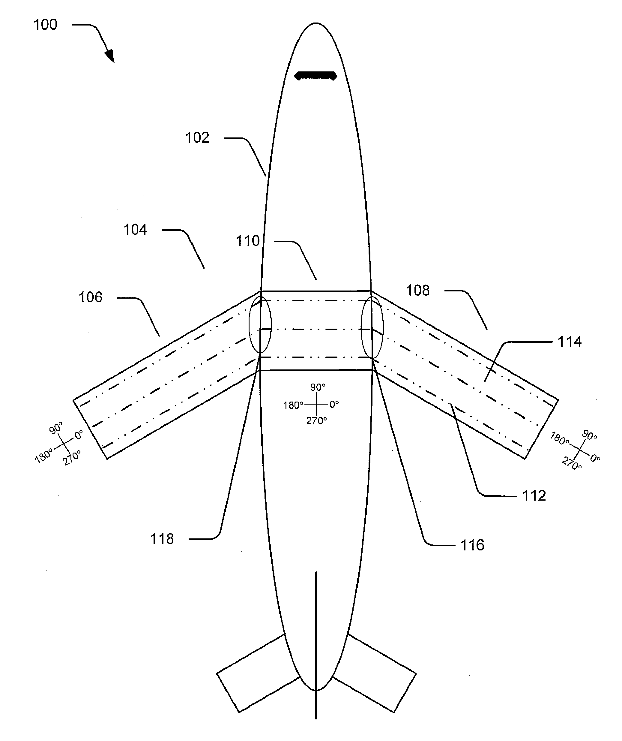
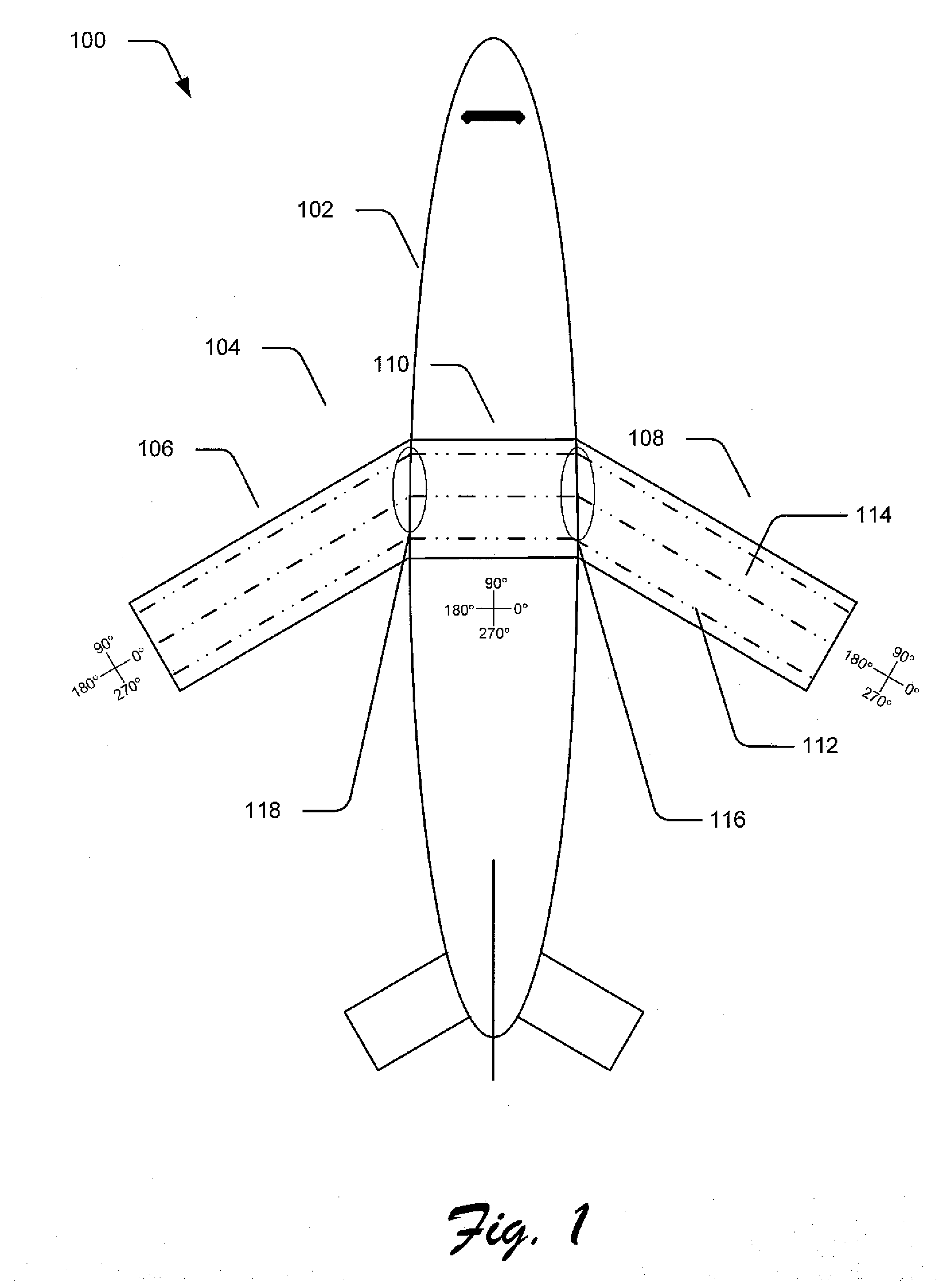
[0012]FIG. 1 illustrates an aircraft 100 in accordance with an embodiment of the present invention. In this embodiment, the aircraft 100 includes a fuselage 102 which is joined to a composite wing structure 104. The composite wing structure 1...


PUM


Abstract

Embodiments of integral composite panels and joints for composite structures are described In one implementation, an integrated panel spanning substantially the entire wingspan of an aircraft, includes at least a center portion and a pair of outwardly projecting wing portions. The portions may include a skin formed from successive layers or plies of composite material which overlap and offset at the joint between respective sections creating a pad-up area to carry loads between the portions. In a particular implementation, the skin is laid over one or more structural stringers which are transitioned into the joints between sections such as by tapering of the thickness and / or stiffness of the stringer.

Description

FIELD OF THE INVENTION[0001]This invention relates to devices and techniques for aerodynamic structures of composite construction and more specifically, to novel, improved integrated composite wings and wing-to-body joints.BACKGROUND OF THE INVENTION[0002]In manufacturing of an aircraft, aerodynamic structures such as wing panels are joined to the fuselage or to other structures of the aircraft. Traditionally, mechanical butt joints are used in which a portion of the wing may be butted up to a portion of the fuselage and joined via mechanical joints, using bolts, rivets and devices such as ribs and so forth. In these traditional butt joints, the bolts and ribs of the joint are used to meet the bearing requirements for the joint. Thus, sufficient bolts and other mechanical fastening devices must be used to meet the bearing allowable for the material used in the aircraft design.[0003]Mechanical joints, particularly those with many bolts, may be very heavy which corresponds to more air...

Claims


Application Information

Patent Timeline
02 Apr 2009
Publication
US20090084899A1
IPC
B64C3/26
CPC
B64C1/26; Y10T428/19; B64C3/26; B64C3/182; Y02T50/40
Inventors
KISMARTON, MAX U.; WESTRE, WILLARD N.