Co-generated power supply system

a power supply system and cogeneration technology, applied in the direction of process and machine control, sustainable manufacturing/processing, instruments, etc., can solve the problems of inability to stably supply electric power, inconvenience, and inability to use dc in the present circumstances of a thyristor phase control system, so as to improve the performance of the whole system, reduce the cost, and save energy

Inactive Publication Date: 2009-04-02
SUZUKI YASUNOBU +1
View PDF12 Cites 22 Cited by
  • Summary
  • Abstract
  • Description
  • Claims
  • Application Information

AI Technical Summary

Benefits of technology

[0014]In view of the foregoing, it is the main object of the present invention to provide a novel co-generated power supply system, in which electric power of a natural energy system having many fluctuation factors is combined with stable electric power such as a battery storing midnight electric power or a fuel cell, so that the stable electric power is supplied to a load via an electronic transformer commonly used at a usage rate of almost 100%, thus reducing the cost and enhancing the performance of the entire system, so as to spread and make more prevalent the co-generated power supply and save the energy.
[0015]According to the novel co-generated power supply system of the present invention, in the case where the electric power is supplied directly to the load from both AC and DC sources as illustrated in FIG. 3, the efficiency can be enhanced by the amount of removed efficiency η1 of the inverter in comparison with the prior art illustrated in FIG. 1. Furthermore, although it might be necessary to insert a device used as both insulator and transformer between the commercial AC power source and the co-generated power equipment for the reason of protection, the efficiency η1 of the DC-AC inverter of several kilowatts or less including an insulating function is about 90% and the efficiency η1′ of the electronic transformer of the same capacity is about 94% to 95%, resulting in η1<η1′. Thus, the system of the present invention can still achieve better efficiency.

Problems solved by technology

Since in these types of natural energy, the duration of sunshine, the operation rate of a windmill or generated electric power fluctuates at all times due to variations in weather or meteorological situations, it is difficult to stably supply electric power.
In contrast, a dimmer, a space heating appliance and an automatic rice cooker of a thyristor phase control system cannot be used with DC under present circumstances.
As a consequence, there has arisen an immediate inconvenience that the appliance only for AC and the household electric appliance for both of AC and DC must be used with separate indoor wiring systems (i.e., receptacles) independent of each other.
However, the DC power generation energy always is reversely converted into the commercial AC through an inverter in the conventional system, and then, is converted into the DC again within an actual load, and further, is converted into a high frequency inverter or a variable frequency AC power, so as to drive an electric motor or a compressor, thereby increasing a conversion loss.
If control equipment such as an inverter is provided for each electric power of the energy generating source of a low operating rate in the above-described manner, the cost of the entire system is increased, thereby leading to one factor of inhibition of popular use.

Method used


Image

  • Co-generated power supply system
  • Co-generated power supply system
  • Co-generated power supply system

Examples


first embodiment

[0033]FIG. 4 is a diagram illustrating a co-generated power supply system in an embodiment according to the present invention.

[0034]In the co-generated power supply system in the embodiment illustrated in FIG. 4, first, DC power sources include a wind turbine generator WTB (Wind Turbine Generator), a solar cell PV (Photo Voltaic) and a fuel cell FC (Fuel Cell) whose rated voltages are made equal to a rated voltage of a storage battery B (Battery). The co-generated power supply system is configured such that AC power from a commercial AC power source Utility is supplied to a load Lac / dc for both AC and DC until the storage battery B is fully charged by the DC power sources WTB, PV and FC; DC power from the storage battery B is supplied to the load Lac / dc for both AC and DC when the storage battery B has been fully charged; and AC power from the commercial AC power source Utility is supplied to the load Lac / dc for both AC and DC as the storage battery B proceeds to be discharged and a...

second embodiment

[0038]FIG. 5 is a diagram illustrating a co-generated power supply system in another embodiment according to the present invention.

[0039]The co-generated power supply system in the embodiment illustrated in FIG. 5 comprises a bidirectional DC-DC converter Conv and a two-winding electronic transformer 2. The two-winding electronic transformer 2 includes a high frequency transformer HFT having the function of matching and insulating a voltage on a side of a storage battery and a voltage on a side of a load; modulation / demodulation semiconductor switches SW3 and SW2 which are connected to a coil on the side of the storage battery and a coil on the side of the load and are operated at 10 kHz to 50 kHz; and a filter F2 connected onto the side of the load.

[0040]The two-winding electronic transformer 2 is used for both AC and DC and has two bidirectional input / output terminals 2a and 2b. One bidirectional input / output terminal 2a is connected to an output side of a DC power source; in cont...

third embodiment

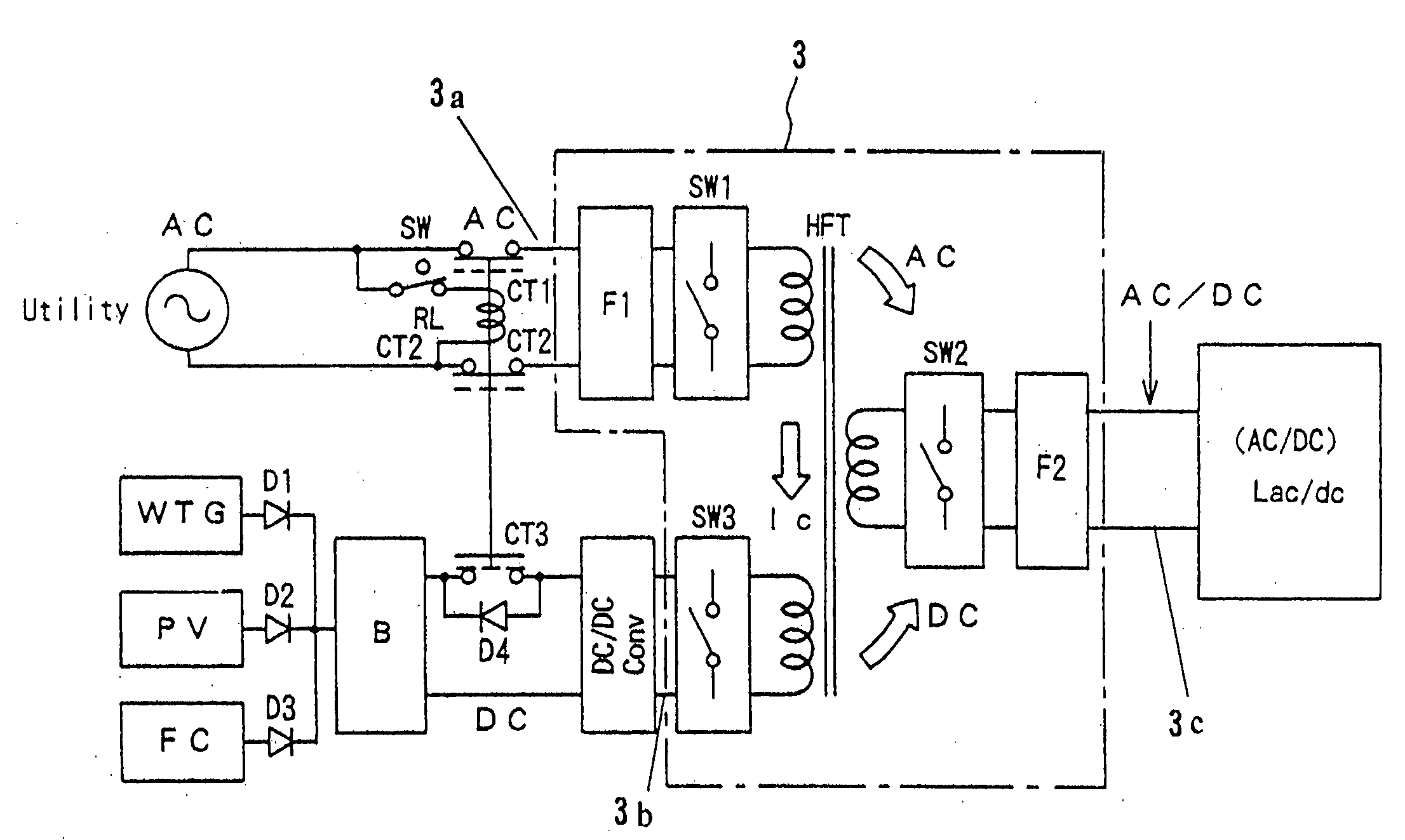
[0044]FIG. 6 is a diagram illustrating a co-generated power supply system in a further embodiment according to the present invention.

[0045]The co-generated power supply system in the embodiment illustrated in FIG. 6 comprises a three-winding electronic transformer 3 having three bidirectional input / output terminals 3a, 3b and 3c for both AC and DC in order to insulate between a commercial AC power source Utility and a load Lac / dc for both AC and DC and adjust for fluctuations in power source voltage, wherein DC power sources WTG, PV and FC and a storage battery B, the commercial AC power source Utility and the load Lac / dc for both of the AC and the DC are connected in a mutually insulating manner. The three-winding electronic transformer 3 includes a high frequency transformer HFT having the function of matching and insulating a voltage on the side of the storage battery and a voltage on the side of the load; modulation / demodulation semiconductor switches SW1, SW3 and SW2 which are ...


PUM

PropertyMeasurementUnit
power generation timeaaaaaaaaaa
frequencyaaaaaaaaaa
AC poweraaaaaaaaaa

Abstract

In a co-generated power supply system for performing dispersed power supply to a load, a wind turbine generator, a solar cell and a fuel cell whose rated voltages are made equal to a rated voltage of a storage battery are used as DC power sources. These DC power sources, a commercial AC power source and the load are connected to each other via a bi-directional electronic transformer. Thus, the co-generated power supply system, in which the electric power of a natural energy system having many fluctuation factors is combined with stable electric power such as a load leveling battery or a fuel cell, allows the stable electric power to be supplied to the load via the electronic transformer commonly, thereby reducing the cost and enhancing the performance of the entire system.

Description

[0001]This application is a divisional application of application Ser. No. 10 / 630,692, filed Jul. 31, 2003.BACKGROUND OF THE INVENTION[0002]1. Field of the Invention[0003]The present invention relates to a novel co-generated power supply system, which is useful for co-generated power supply of a combination of natural energy and stable energy such as a fuel cell and power storage energy during the nighttime and midnight, and especially, which can efficiently supply electric power to a load by connecting a plurality of AC and DC energy sources to each other via an electronic transformer, a diode and an OR circuit.[0004]2. Description of the Related Art[0005]As a typical example of clean energy, the solar cell has been prevalant. Furthermore, the wind turbine generator has been introduced in local regions. Since in these types of natural energy, the duration of sunshine, the operation rate of a windmill or generated electric power fluctuates at all times due to variations in weather o...

Claims


Application Information

Patent Timeline
Patent Type & Authority Applications(United States)
IPC IPC(8): H02J3/32H01L31/04H01M8/00H01M8/04H02J3/38H02J7/00H02J7/34H02J7/35H02M3/335
CPCH02J3/38H02J7/0055H02J7/34Y02E10/766H02M3/33584Y02E10/763H02J2007/0059H02J2207/20H02J2207/40H02J2300/40Y02E10/56Y02E10/76Y02P80/20Y02P90/40H02J9/067
Inventor SUZUKI, YASUNOBUTESHIMA, TORU
Owner SUZUKI YASUNOBU
Why Eureka
Try Eureka