On-vehicle LED illumination device

a technology of led lamps and led lamps, which is applied in the direction of electroluminescent light sources, light sources, instruments, etc., can solve the problems of increased manufacturing costs, difficulty in obtaining, and inability to obtain sufficient light intensity from led lamps, so as to prevent excessive heating

Inactive Publication Date: 2009-04-02
TOYODA GOSEI CO LTD
View PDF6 Cites 26 Cited by
  • Summary
  • Abstract
  • Description
  • Claims
  • Application Information

AI Technical Summary

Benefits of technology

[0033]In this manner, when the PTC thermistor is operated at the environmental tempe...

Problems solved by technology

First, it is difficult to obtain, from a single current LED lamp, a light intensity almost same as that of a bulb-type lamp.
However, a sufficient light intensity cannot be obtained from the LED lamp to which a small amount of...

Method used


Image

  • On-vehicle LED illumination device
  • On-vehicle LED illumination device
  • On-vehicle LED illumination device

Examples


Embodiment Construction

[0041]Hereinafter, embodiments according to the invention will be explained with reference to drawings.

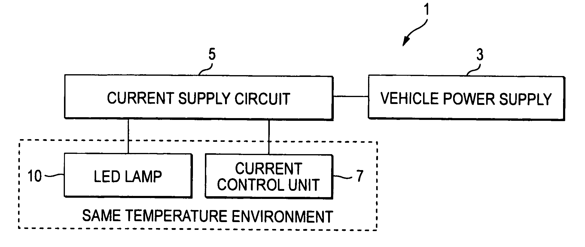
[0042]FIG. 1 is a block diagram showing the configuration of the illumination device 1 according to the embodiment.

[0043]The illumination device 1 according to the embodiment includes a current supply circuit 5 for supplying a stable current to an LED lamp 10 from a vehicle power supply 3 and a current control unit 7 for controlling a current supplied to the LED lamp 10 so as to be inversely proportional to the environmental temperature of the LED lamp 10.

[0044]Although the luminescent color of the LED lamp 10 can be selected arbitrarily, since the lamp emits white light in this embodiment, an LED chip (light source portion) is employed which is formed by combining a semiconductor light emitting element for outputting a short-waveform light or a blue light with a phosphor layer for converting the wavelength of the light emitted from the light emitting element. A III-group nitride c...


PUM


Abstract

An LED illumination device 1 for vehicle use includes an LED lamp 10, a circuit 5 for supplying a current to the LED lamp from a power supply mounted on the vehicle, and a current control unit 7 for controlling the current supplied to the LED lamp 10 so as to be inversely proportional to the environmental temperature of the LED lamp 10. In this manner, in the current supply circuit, an LED chip 11 is coupled to the collector of a common-emitter type transistor 15. The current control unit includes a PTC thermistor 21 and the PTC thermistor 21 is coupled to the base of the transistor 15, whereby a current supplied to the base is made small when the temperature of the PTC thermistor 21 becomes high. The PTC thermistor 21 is placed in a circumstance where the temperature thereof becomes same as the environmental temperature of the LED chip 11 at the time where the LED chip 11 is in an OFF state.

Description

BACKGROUND OF THE INVENTION[0001]1. Field of the Invention[0002]The present invention relates to an LED illumination device for vehicle use.[0003]2. Description of the Related Art[0004]In general, bulb type lamps have been employed as illumination devices for vehicle use such as room lamps, map lamps, reading lamps.[0005]As a recent tendency, LED lamps have been noticed as light sources within vehicles in view of power saving, miniaturizing and light-weighting, and long living etc.[0006]The documents disclosing the technique relating to the invention are a patent document 1 and a patent document 2.[0007]Patent Document 1: JP-A-9-325719[0008]Patent Document 2: JP-A-2007-87720[0009]The inventors of the present application have concentrated on the investigation of LED lamps so as to utilize the LED lamp as a light source of an on-vehicle illumination device.[0010]First, it is difficult to obtain, from a single current LED lamp, a light intensity almost same as that of a bulb-type lamp....

Claims


Application Information

Patent Timeline
IPC IPC(8): H05B37/02H05B45/50
CPCH05B33/089H05B33/0854H05B45/50H05B45/18
Inventor NARITA, TAKUMIFUKI, SHINICHIROSAKAI, KAZUHIRO
Owner TOYODA GOSEI CO LTD
Why Eureka
Try Eureka