Capacitive Touch Panel with Low Impedance

Active Publication Date: 2009-04-02
AU OPTRONICS CORP
View PDF12 Cites 160 Cited by
  • Summary
  • Abstract
  • Description
  • Claims
  • Application Information

AI Technical Summary

Benefits of technology

[0008]It is an objective of the present invention to provide a capacitive t

Problems solved by technology

However the resistive touch panel 30 cannot accept multi-input simultaneously and also cannot process fingerprint recognition.
Excessive amount of electrodes 31 on the same row or the same column may result in excessive res

Method used


Image

  • Capacitive Touch Panel with Low Impedance
  • Capacitive Touch Panel with Low Impedance
  • Capacitive Touch Panel with Low Impedance

Examples


Embodiment Construction

[0032]The present invention provides a capacitive touch panel and a display device incorporating the capacitive touch panel. The capacitive touch panel of the present invention includes an external adhesive capacitive touch panel and a capacitive touch panel integrated into a panel of display device. Furthermore, the above-mentioned display device mentioned includes a flat panel display device but is not limited thereto. The display panel is preferred to include a LCD panel, Organic Light Emitting Diode (OLED) display panel or other display panels. Furthermore, the LCD panel includes transmissive LCD panels, reflective LCD panels, transflective LCD panels and other types of LCD panel.

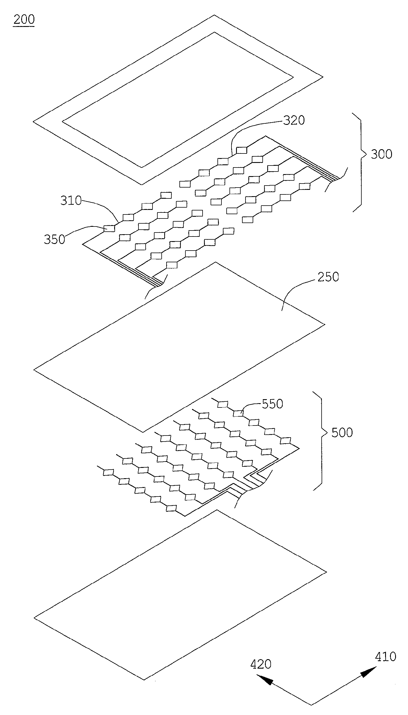
[0033]In an embodiment shown in FIG. 2, the display device 100 includes a display panel 110 and a capacitive touch panel 200. The capacitive touch panel 200 is preferred to be disposed on a display surface 111 of the display panel 110. The images of display panel 110 on the display surface 111 are displ...


PUM

PropertyMeasurementUnit
Electrical conductoraaaaaaaaaa
Distributionaaaaaaaaaa
Electric impedanceaaaaaaaaaa

Abstract

A capacitive touch panel and a display device using the capacitive touch panel are provided. The capacitive touch panel includes a first electrode layer, a second electrode layer, and a dielectric layer disposed between two layers. The first electrode layer has a plurality of first A electrode strings and first B electrode strings extended along a first direction. The first A electrode string and the first B electrode string respectively has a plurality of first direction electrodes. The second electrode layer has a plurality of second direction electrodes connected in series along a second direction. The first A and B electrode strings are disconnected in the first electrode layer while they are simultaneously detected for presence of signal variation.

Description

BACKGROUND OF THE INVENTION[0001]1. Field of the Invention[0002]The present invention relates to a capacitive touch panel and a display device using the capacitive touch panel.[0003]2. Description of the Prior Art[0004]Display panels and flat screen display device using display panels are becoming the mainstream in the field of display devices. For instance, flat television for home use, liquid crystal monitor of the personal computer or of the laptop, display screen of mobile phone and digital camera are products which incorporate the display panel as essential component. As the product design is becoming user-oriented, the usability of the product calls for the touch input function of the display panel which becomes an emphasis in the development of the display device industry.[0005]As FIG. 1a shows, conventional Liquid Crystal Display (LCD) panel of with touch-input function includes a display panel 10 and a touch sensor 30. The touch panel 30 is disposed on the display surface 1...

Claims


Application Information

Patent Timeline
IPC IPC(8): G06F3/044H01H11/00H01G5/16
CPCG06F3/044Y10T29/43Y10T29/49105H03K17/9622G06F3/0445G06F3/0446G01R31/28G06F3/0412G06F3/045G06F2203/04103G06F2203/04106G06F2203/04112G09G3/36
Inventor YANG, TUN-CHUNLEE, SEOK-LYULHU, CHIH-JENCHENG, KUO-HSINGHSIEH, YAO-JENMA, MEI-SHENGLEE, HSIN-HUNGWU, YUAN-CHUNLI, CHUN-HUAI
Owner AU OPTRONICS CORP
Why Eureka
Try Eureka