Inkjet recording head and inkjet recording apparatus having the same

Inactive Publication Date: 2009-04-02
CANON KK
View PDF13 Cites 21 Cited by
  • Summary
  • Abstract
  • Description
  • Claims
  • Application Information

AI Technical Summary

Benefits of technology

[0020]The present invention provides an inkjet recording head that overcomes the above-described problems and that can accura

Problems solved by technology

Further, if a minute bubble, which grows in the ink in the ink passage for discharging, remains in the ink passage, normal ink discharging is sometimes difficult.
This phenomenon of defective discharging due to the remaining bubble pronouncedly appears when the print duty is relatively high.
In another case, a bubble enters the ink at a connecting portion of an ink supply passage or an ink supply system, and clogs the ink supply passage.
If recording failure is caused by the above-described defective ink discharging, the recording medium is wasted, and the time taken for recording is also wasted.
If unclear images are continuously recorded in a so-called “faded recording” state caused immediately before defective discharging occurs, multiple recording media are wasted.
Further, if recording is continued in the “faded recording” state, the recording head is heavily loaded, and this sometimes destroys the recording head itse

Method used


Image

  • Inkjet recording head and inkjet recording apparatus having the same
  • Inkjet recording head and inkjet recording apparatus having the same
  • Inkjet recording head and inkjet recording apparatus having the same

Examples


first embodiment

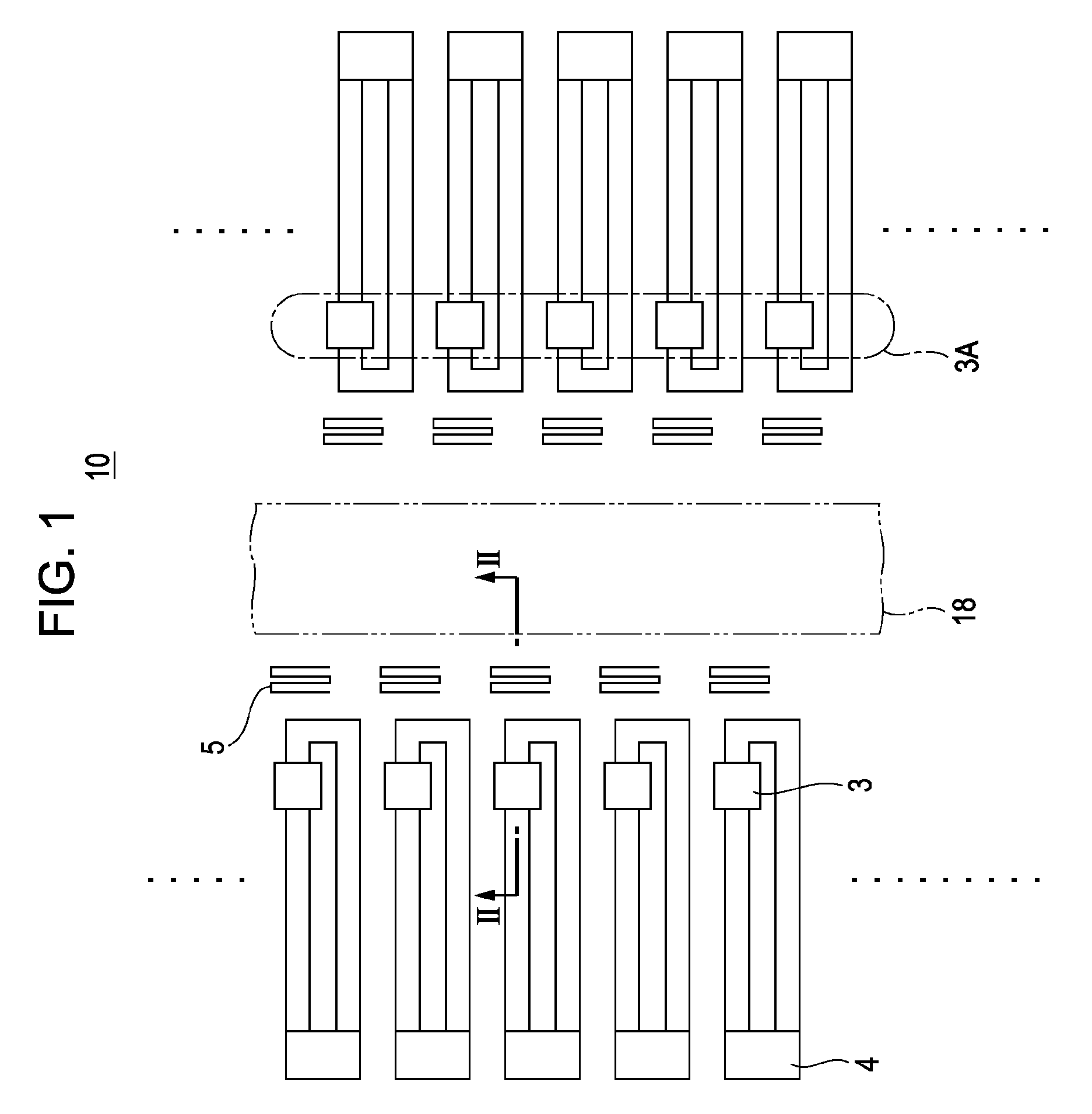
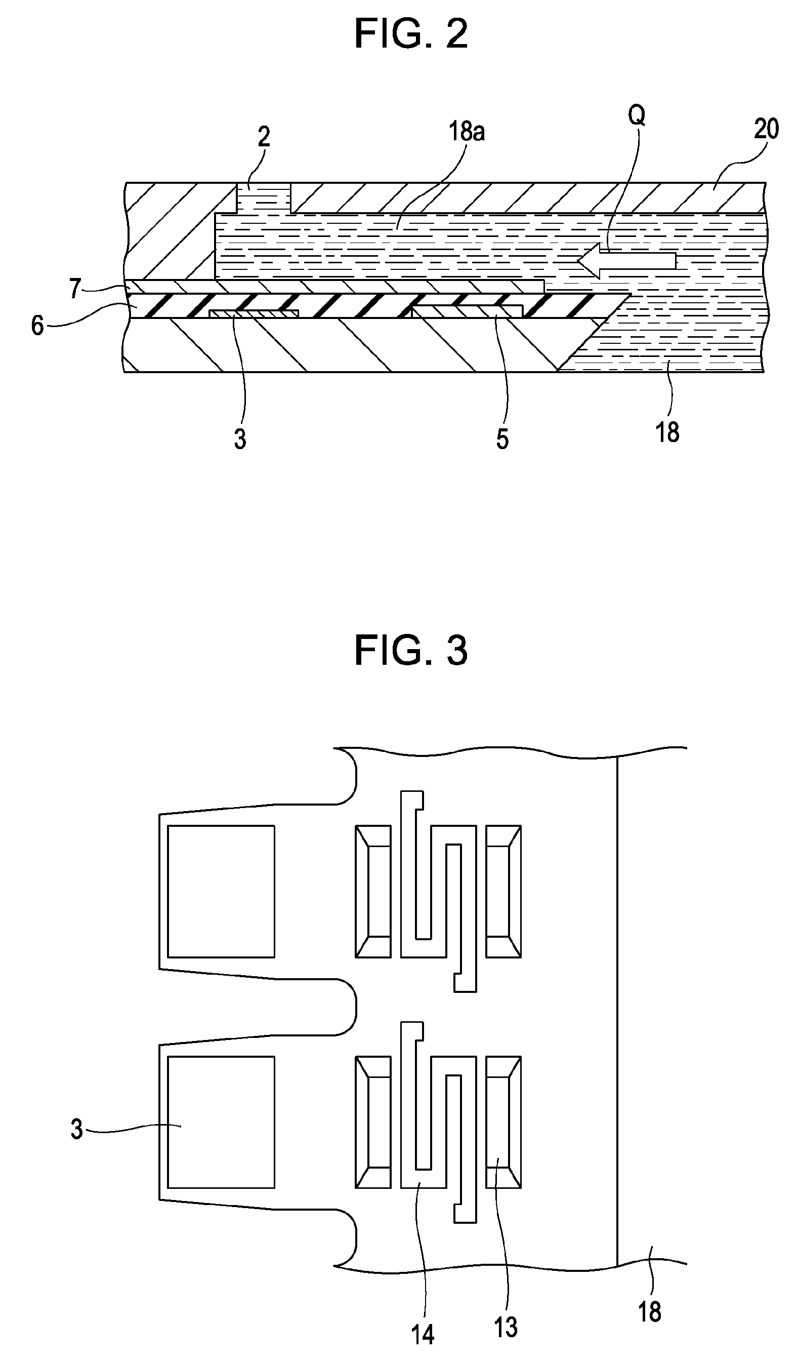
[0054]FIG. 1 is a schematic view showing a part of a substrate in an inkjet recording head according to a first embodiment of the present invention. FIG. 2 is a cross-sectional view of the substrate, taken along line II-II in FIG. 1.

[0055]Referring to FIG. 1, a heater board 10 has a structure in which a common liquid chamber 18 is provided at the center thereof, as viewed in a direction perpendicular to the board surface. On each side of the common liquid chamber 18 in the heater board 10, a heater unit 3A including a plurality of discharging heaters 3 arranged in line is provided.

[0056]Dummy resistors (not shown) are provided near the heater units 3A. The dummy resistors are not used for discharging of ink droplets. The discharging heaters 3 are electrothermal transducers (discharging-energy generating elements) that generate heat energy in accordance with the applied voltage, and are connected to terminals 4 to which a driving signal is applied. The terminals 4 are connected to ex...

second embodiment

[0112]An inkjet recording head according to a second embodiment has a basic configuration similar to that of the recording head of the first embodiment except in an operation of detecting defective discharging with a flow sensor. The inkjet recording head of the second embodiment also includes an ink-flow detector (ink-flow detecting unit) similar to that shown in FIG. 5.

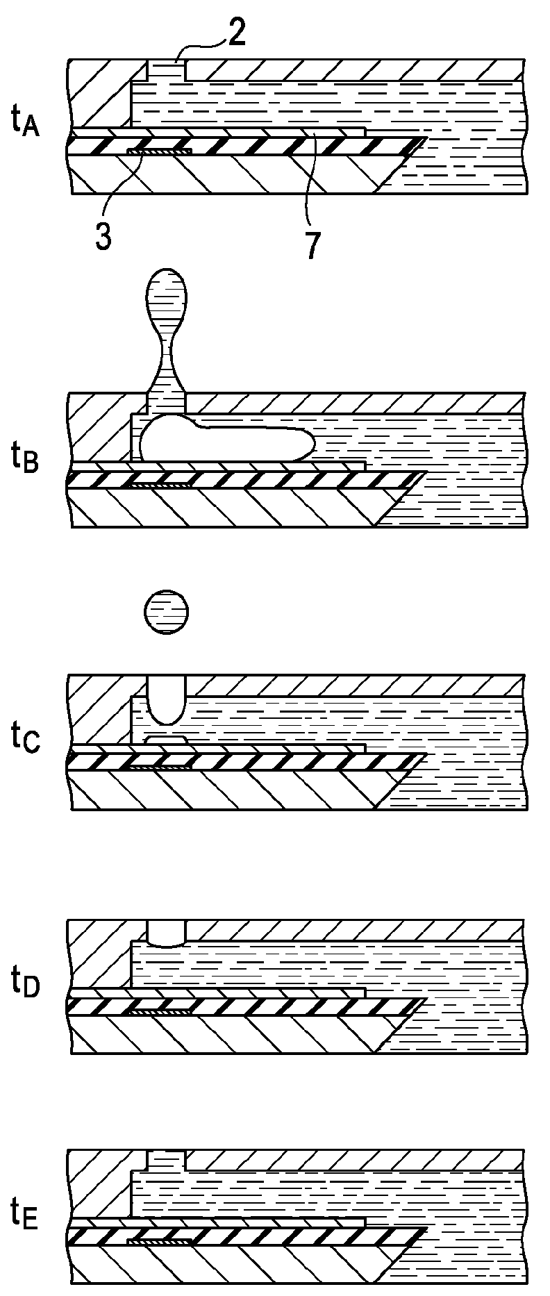
[0113]FIGS. 9A to 9E explain the principle of operation of the ink-flow detector. FIG. 9A is a waveform chart of the voltage applied to the electrothermal transducer 15. FIG. 9B shows the change in ink flow rate on the time axis when the direction from the common liquid chamber 18 to the discharge port 2 shown in FIG. 1 is a positive direction. FIG. 9C is a waveform chart of the current applied to the detecting element 17. FIG. 9D shows the change in temperature on the time axis of ink on the detecting element 17. FIG. 9E is a waveform chart of the detected output voltage in accordance with the changes in ink flow r...

third embodiment

[0119]FIG. 10 is a partial sectional view of an inkjet recording head according to a third embodiment of the present invention. In this recording head, a nozzle forming member 20 that defines a passage by being combined with a heater board (head substrate) is not formed of an organic material, but of silicon (Si). In this nozzle forming member 20, a flow sensor 5 serving as an ink flow-rate detecting element is formed by a film deposition process similar to the process for a semiconductor. Other structures are similar to those adopted in the first embodiment.

[0120]The flow sensor 5 may have a meandering shape in order to increase the resistance, or may have a square shape.

[0121]The inkjet recording head of the third embodiment also includes an ink-flow detector having a configuration similar to that shown in FIG. 5. The ink-flow detector operates in a manner similar to that adopted in the first embodiment.

[0122]Since the flow sensor 5 is provided apart from a discharging heater 3 in...


PUM


Abstract

An inkjet recording head includes a passage communicating with a discharge port for discharging ink, a discharging heater provided in the passage for generating energy to discharge ink from the discharge port, and a detecting unit provided in the passage for detecting a temperature of ink that changes in accordance with heat energy generated by the detecting unit and a flow of ink in the passage.

Description

BACKGROUND OF THE INVENTION[0001]1. Field of the Invention[0002]The present invention relates to inkjet recording apparatuses, and more particularly, to an inkjet recording apparatus that can detect defective discharging. Herein, the term “recording” includes applications of ink (printing) to ink support materials such as cloth, strings, paper, and sheet materials. The term “recording apparatus” includes various information apparatuses and printers serving as output devices of the apparatuses.[0003]2. Description of the Related Art[0004]Along with the popularization of information processing apparatuses such as copying machines, word processors, and computers, recording apparatuses (inkjet recording apparatuses) that perform recording with an inkjet recording head have been rapidly popularized as output (recording) apparatuses for the information processing apparatuses.[0005]In general, an inkjet recording apparatus includes a carriage on which a recording head and an ink tank are m...

Claims


Application Information

Patent Timeline
IPC IPC(8): B41J29/38
CPCB41J2/0451B41J2/04541B41J2/04588B41J2/0458B41J2/04573B41J2/14153B41J2002/14354
Inventor AOKI, TAKATSUNAKANNO, HIDEO
Owner CANON KK
Why Eureka
Try Eureka