Exhaust flue cap and filter device for a gas fired appliance

a technology of exhaust flue cap and filter device, which is applied in the direction of lighting and heating apparatus, combustion types, separation processes, etc., can solve the problems of gas fired appliances, which do not produce the extensive amount of soot or other emissions, and produce a certain amount of particulate emissions and carbon monoxide emissions, so as to reduce carbon monoxide and unburned hydrocarbons

Active Publication Date: 2009-04-02
ARNOLD JOHN G JR
View PDF26 Cites 27 Cited by
  • Summary
  • Abstract
  • Description
  • Claims
  • Application Information

AI Technical Summary

Benefits of technology

[0013]The present invention is directed to an exhaust flue cap and filter device for a gas fired appliance and to a process or method to reduce carbon monoxide and unburned hydrocarbon emissions from the exhaust of a gas fired appliance.
[0016]A filter tray is suspended within the tubular cap and has a smaller diameter than the tubular cap. The filter tray may be suspended within the tubular cap by a series of standoffs. The filter tray has an open bottom and an open top and may include a downwardly and outwardly extending flared skirt to discourage rain or precipitation from entering the exhaust vent pipe and also to encourage flue gas to pass through the filter tray.

Problems solved by technology

For the most part, gas fired appliances are relatively efficient and do not produce the extensive amount of soot or other emissions associated with wood burning fireplaces and stoves or with coal burning fireplaces or stoves.
Even gas fired appliances, however, produce a certain amount of particulate emissions and carbon monoxide emissions.

Method used


Image

  • Exhaust flue cap and filter device for a gas fired appliance
  • Exhaust flue cap and filter device for a gas fired appliance
  • Exhaust flue cap and filter device for a gas fired appliance

Examples


second embodiment

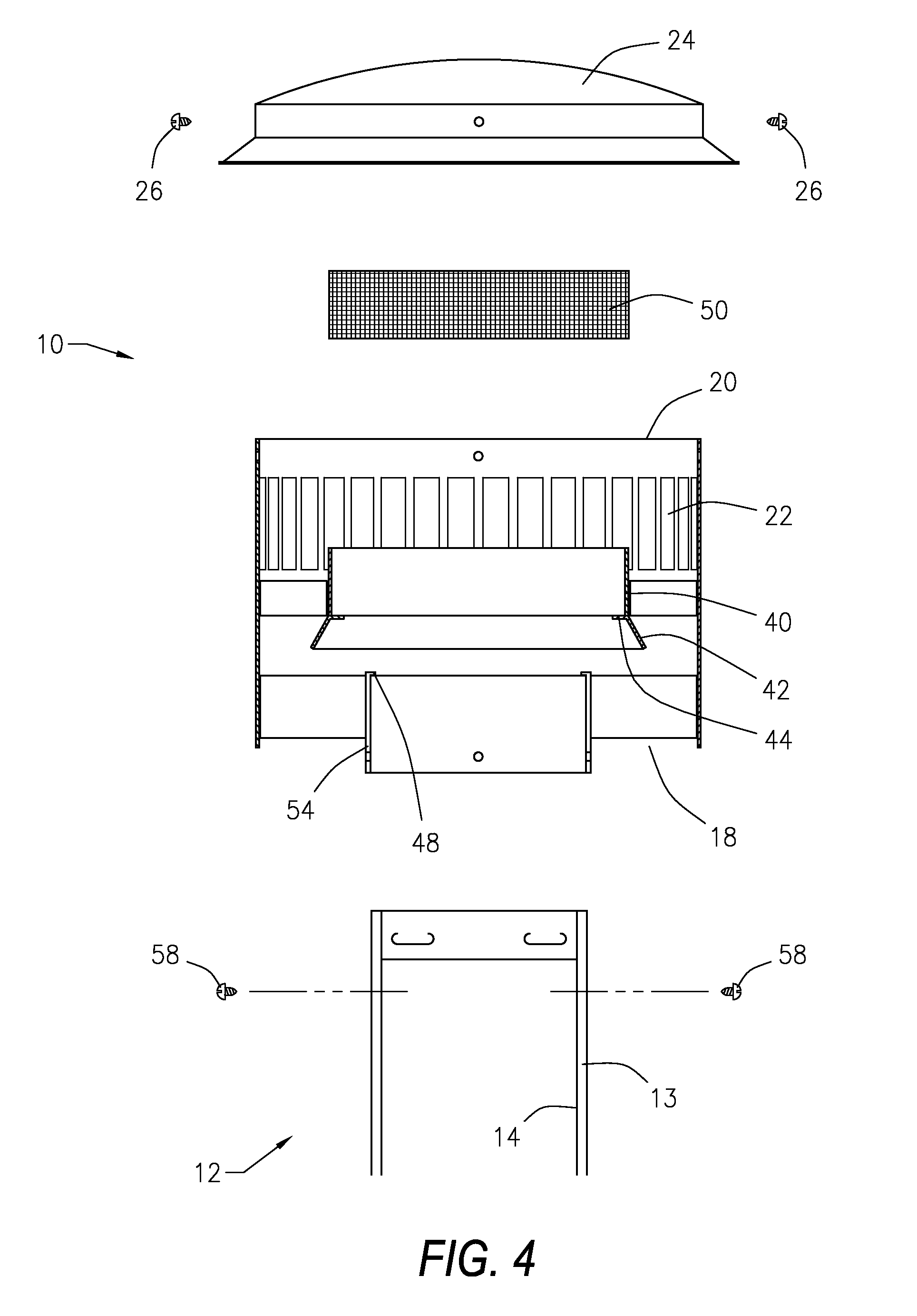
[0047]In a second embodiment, the filter insert 50 may be comprised of a ceramic block monolith having a honeycomb structure with gas flow passages which are coated with a washcoat having a precious metal catalyst.

third embodiment

[0048]In a third embodiment, the filter insert 50 is comprised of a metal foam with between three to five pores per inch. The filter insert includes a washcoat having a precious metal catalyst.

[0049]In a fourth configuration, the filter insert may take the form of multiple ceramic discs which are coated with a washcoat having a precious metal catalyst. In each case, the washcoat may be alumina based.

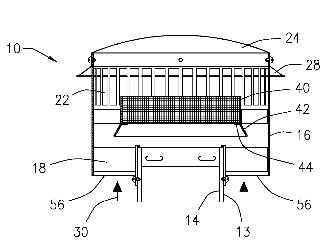
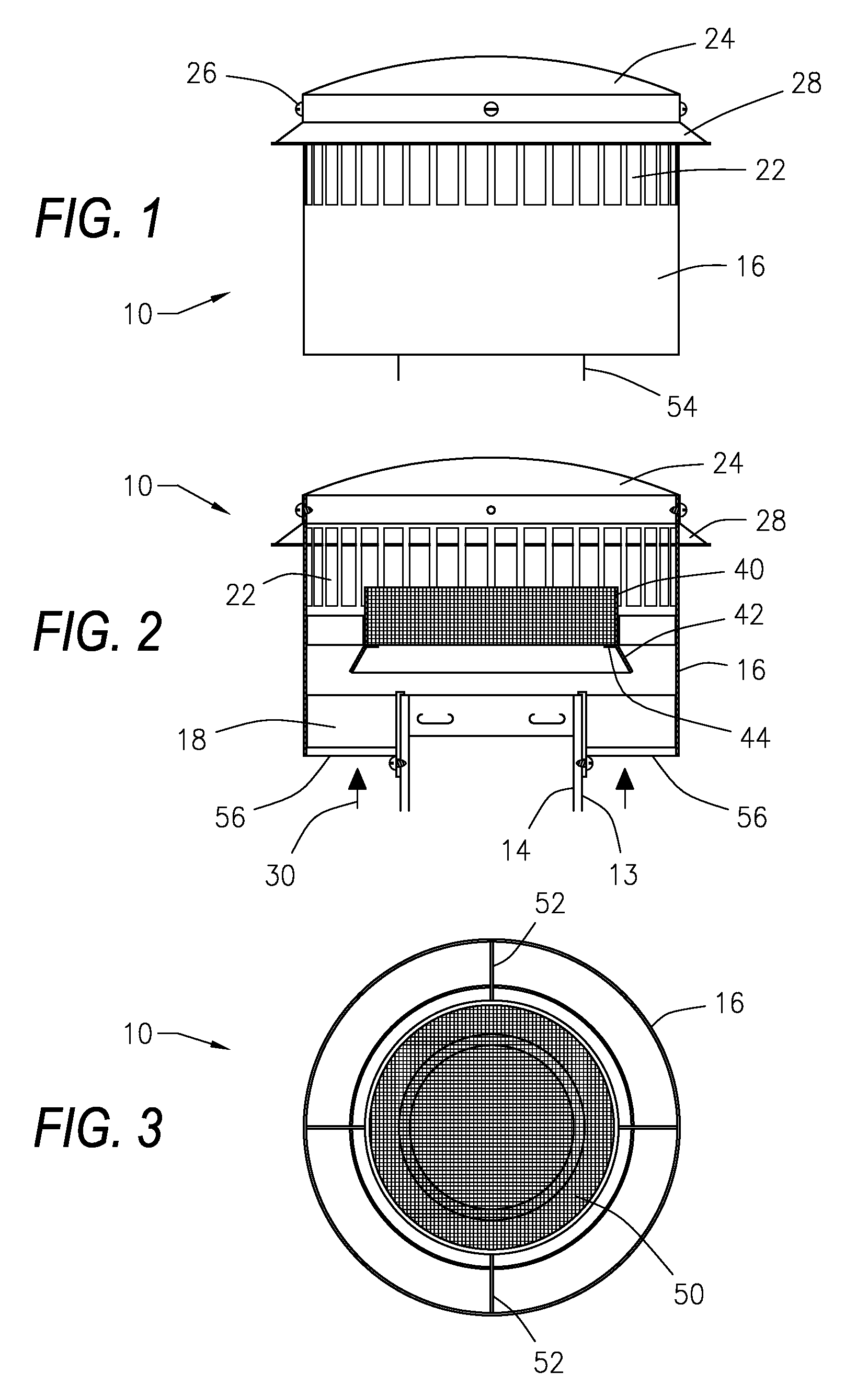
[0050]In use, exhaust gases are passed from a gas fired appliance (not shown) through the exhaust vent system 12 flue opening into the tubular cap 16 so that exhaust gases mix with atmospheric air entering the open lower end of the tubular cap 16. The atmospheric air and exhaust gases pass into and through the catalytic filter insert 50 in the tray. The exhaust gases are treated by the catalytically active filter insert 50 which promotes oxidation in order to convert excess carbon monoxide (CO) into carbon dioxide (CO2). The treated gases are thereafter permitted to move from the upper e...


PUM

PropertyMeasurementUnit
diameteraaaaaaaaaa
shapeaaaaaaaaaa

Abstract

An exhaust flue cap and filter device for a gas fired appliance in communication with an exhaust flue opening having an outer pipe and a coaxial liner. The device includes a tubular cap with an open lower end, an opposed open upper end, and a plurality of ventilation holes wherein the cap is receivable over the flue opening. A removable top is attached to and closes the open upper end of the tubular cap. A filter tray having a smaller diameter than the tubular cap includes a ledge extending radially inward from the tray. A removable catalytic converter filter insert within the tubular cap is supported on the ledge.

Description

CROSS-REFERENCE TO PENDING APPLICATIONS[0001]This application is based on and is entitled to the filing date of U.S. Provisional Patent Application Ser. No. 60 / 975,693 filed Sep. 27, 2007.BACKGROUND OF THE INVENTION[0002]1. Field of the Invention[0003]The present invention is directed to an exhaust flue cap and filter device or appliance and a method of use for an exhaust flue opening of a gas fired appliance. In particular, the present invention is directed to an exhaust flue cap and filter device which will reduce carbon monoxide and particulate emissions from the exhaust of a gas fired appliance.[0004]2. Prior Art[0005]There are various types of known gas fired appliances that are used with buildings and residences. These include gas fired water heaters, gas fired boilers, gas fired fireplaces, gas logs fitted within fireplaces, gas fired air heating systems, gas fired clothes dryers, or other apparatus that use gaseous hydrocarbon fuels such as natural gas or propane.[0006]For t...

Claims


Application Information

Patent Timeline
Patent Type & Authority Applications(United States)
IPC IPC(8): F23J13/08
CPCB01D53/864B01D53/885B01D2255/10B01D2255/2092F23L17/02F23J15/02F23J15/025F23J2217/10F23J2900/13004F23G7/07
Inventor ARNOLD, JR., JOHN G.SMITH, JOSEPH D.
Owner ARNOLD JOHN G JR
Why Eureka
Try Eureka