Method and System to Mitigate Deposit Formation on a Direct Injector for a Gasoline-Fuelled Internal Combustion Engine

a direct injection, gasoline-fuelled technology, applied in the direction of electrical control, process and machine control, instruments, etc., can solve the problems of low degree of flexibility of di, high degree of variability in pulse-to-pulse fuel delivery quantity, and less time available for fuel injection to take place. , to achieve the effect of mitigating the formation of deposits

Inactive Publication Date: 2009-04-09
FORD GLOBAL TECH LLC
View PDF12 Cites 30 Cited by
  • Summary
  • Abstract
  • Description
  • Claims
  • Application Information

AI Technical Summary

Benefits of technology

[0006]The inventor of the present invention recognizes that it is advantageous to prevent the formation of deposits as opposed to burning off the deposits once formed. To mitigate the formation of deposits, the temperature of the injector tip is maintained below a threshold temperature so that the fuel at the tip is sufficiently cool so that the reactions which lead to deposit formation do not occur.

Problems solved by technology

A drawback of direct injection, however, is that there is less time available for the fuel injection to take place compared to port injection.
However, DI is not so flexible.
Furthermore, there are mixing limitations placed upon fuel injection during the intake and compression strokes in that the injection timing affects the homogeneity achieved at the time of spark firing.
Due to the limitations on DI timing, obtaining the appropriate amount of fuel for the lowest fuel delivery and highest fuel delivery requirements is a challenge with DI.
That is, due to DI's limitations in injection pulse width to meet the highest injection demands causes the pulse widths at the lowest injection demands to be in a nonlinear range of the injector, meaning a high degree of variability in the pulse-to-pulse fuel delivery quantity.
During periods in which the direct injector has no fuel flow through it, the injector is no longer provided cooling by the fuel flow.
The fuel trapped at the injector tip can get very hot and undergo chemical reactions which cause deposit buildup.
Additionally, deposits can from on the tip's external surface also having the effect of reducing the effective cross-sectional area of the injector orifices and / or interfering with the injector spray pattern.
First, such a proposal can only remove accumulated deposits that form on the outside surfaces of the injector, i.e., deposits that are in communication with oxygen so that they can be burned.
Secondly, depending on the operating condition of the engine when such a requirement for increasing injector tip temperature is demanded can lead to a reduction in fuel economy.

Method used


Image

  • Method and System to Mitigate Deposit Formation on a Direct Injector for a Gasoline-Fuelled Internal Combustion Engine
  • Method and System to Mitigate Deposit Formation on a Direct Injector for a Gasoline-Fuelled Internal Combustion Engine
  • Method and System to Mitigate Deposit Formation on a Direct Injector for a Gasoline-Fuelled Internal Combustion Engine

Examples


Embodiment Construction

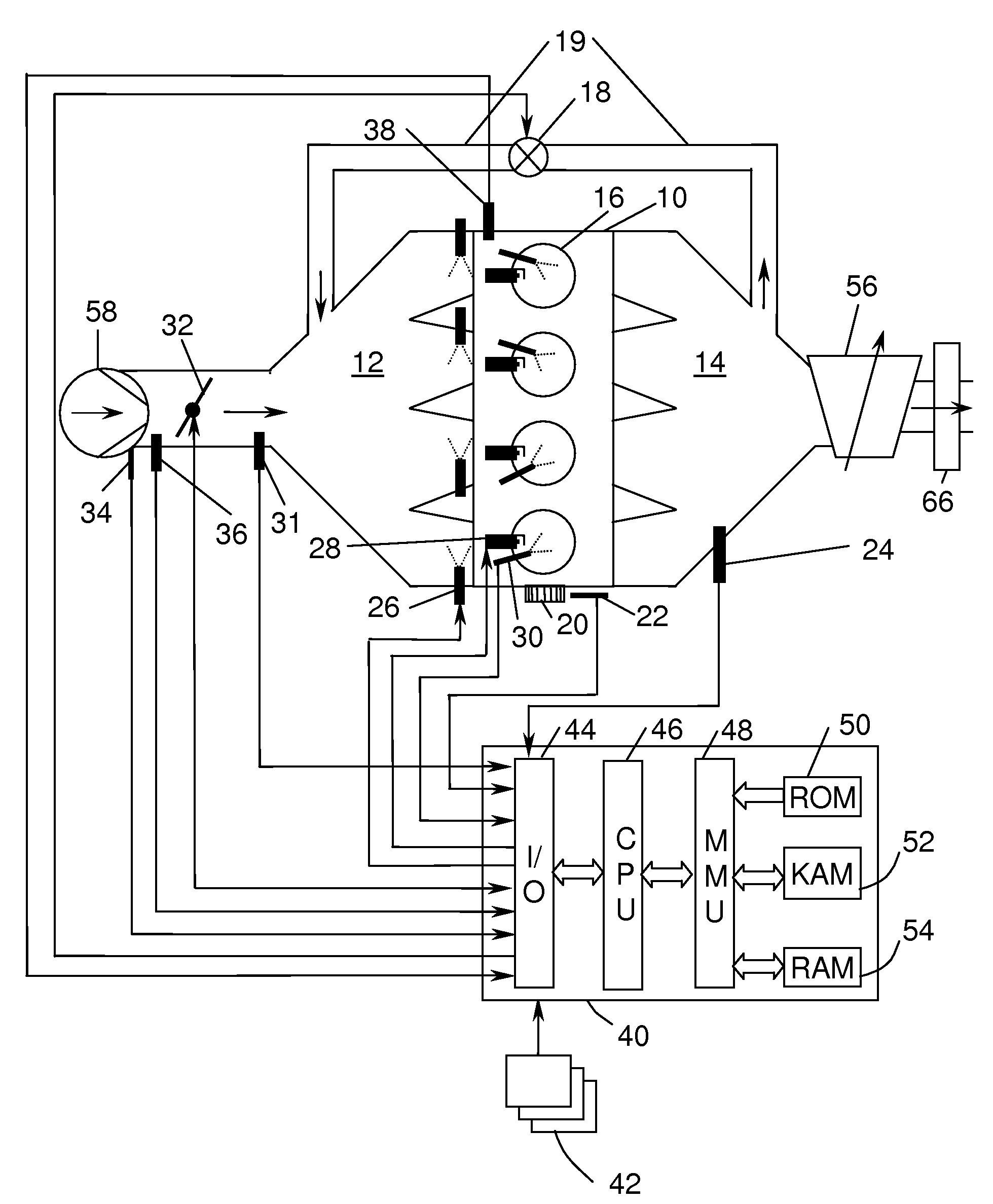
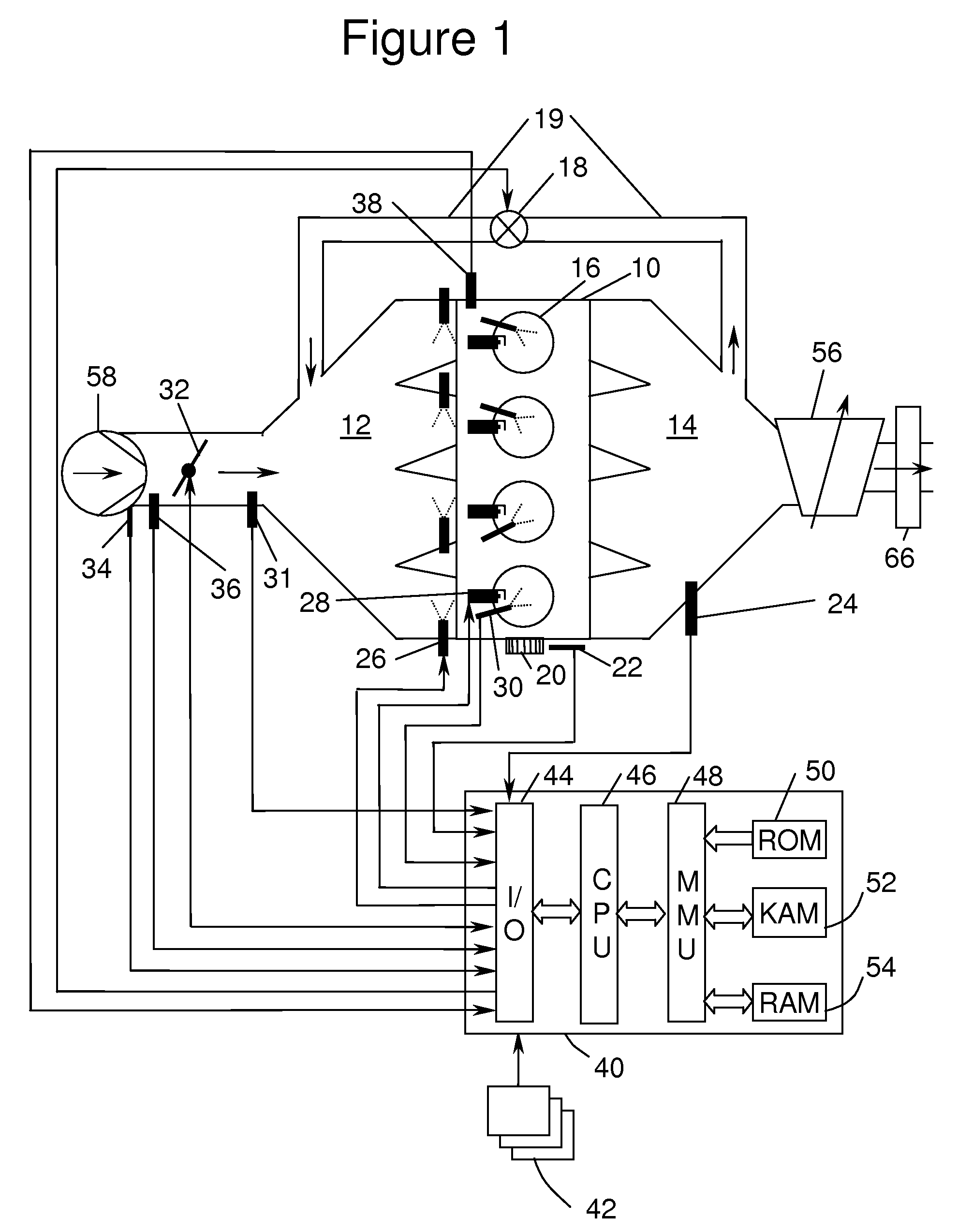
[0014]A 4-cylinder internal combustion engine 10 is shown, by way of example, in FIG. 1. Engine 10 is supplied air through intake manifold 12 and discharges spent gases through exhaust manifold 14. An intake duct upstream of the intake manifold 12 contains a throttle valve 32 which, when actuated, controls the amount of airflow to engine 10. Sensors 34 and 36 installed in intake manifold 12 measure air temperature and mass air flow (MAF), respectively. Sensor 31, located in intake manifold 14 downstream of throttle valve 32, is a manifold absolute pressure (MAP) sensor. A partially closed throttle valve 32 causes a pressure depression in intake manifold 12 compared to the pressure on the upstream side of throttle valve 32. When a pressure depression exists in intake manifold 12, exhaust gases are caused to flow through exhaust gas recirculation (EGR) duct 19, which connects exhaust manifold 14 to intake manifold 12. Within EGR duct 19 is EGR valve 18, which is actuated to control EG...


PUM


Abstract

In an internal combustion engine having both a port injector and a direct injector supplying fuel to a cylinder of the engine, a method is disclosed for avoiding deposit formation on and / or inside the tip of the direct injector. The tip temperature is estimated. When the tip temperature exceeds a threshold temperature at which deposits are formed, the amount of fuel delivered by the direct injector is increase.

Description

FIELD OF THE INVENTION[0001]Deposits can form on and in injectors which are disposed within a combustion chamber of a gasoline-fuelled engine. The present invention concerns mitigating such deposit formation.BACKGROUND OF THE INVENTION[0002]Direct injection (DI) for gasoline-fuelled engines present a fuel economy benefit by providing charge cooling, thereby allowing a modest increase in compression ratio. A drawback of direct injection, however, is that there is less time available for the fuel injection to take place compared to port injection. That is, with a port injected engine, the fuel injection pulse width can comprise almost 720 crank degrees. The fuel sprayed in the port during a period when the intake valve is closed is inducted during the next induction stroke. However, DI is not so flexible. For example, fuel which is to participate in the combustion event cannot be injected during a period in which exhaust gases are flowing out of the cylinder. Furthermore, there are mi...

Claims


Application Information

Patent Timeline
Patent Type & Authority Applications(United States)
IPC IPC(8): F02M63/02
CPCF02B2075/125F02B2275/16F02D35/025F02D41/221Y02T10/123F02D41/40F02D2041/2065F02M25/0707Y02T10/44F02D41/3094F02M26/05Y02T10/12Y02T10/40
Inventor BREHOB, DIANA D.
Owner FORD GLOBAL TECH LLC
Why Eureka
Try Eureka