Optical information recording medium, image-recording method and method of utilizing a dye

Inactive Publication Date: 2009-04-09
FUJIFILM CORP
View PDF4 Cites 0 Cited by
  • Summary
  • Abstract
  • Description
  • Claims
  • Application Information

AI Technical Summary

Benefits of technology

[0009]That is, an object of the invention is to provide an optical information recording medium which permits formation of a distinct, highly contrasty visible image in an image recording layer provided in addition to an optical information recording layer (preferably on the opposite side to the recording side) by using a laser light, and an image recording method of recording an image onto an image recording layer of the optical information recording medium, which method can minimize the hardware source for the recording apparatus and enables a general user to record an image with ease using the recording apparatus.
[0012]The visual information recording layer of the optical recording medium according to the invention requires properties different from those required in typical digital data recording in the following respects: That is, in digital data recording, a pit is formed by one laser light irradiation. Therefore, a typical optical recording medium used in digital data recording and the optical recording medium of the invention require different properties. Typically, when a pit is formed in a dye recording layer, it is important to form a pit that provides sufficient reflectance and a sufficient degree of modulation so that a drive can recognize the pit. Therefore, those skilled in the art will not envision to use the system in which a substantially same track is irradiated with laser light several times, or the system in which laser light swings in the radial direction of an optical disc and a substantially same track is irradiated with the laser light several times. Also, for a typical optical disc, since the position where a pit is formed in the radial direction will be specified, the laser light will never be controlled to swing in the radial direction of the optical disc, or those skilled in the art will never envision to swing the laser light in the radial direction of the optical disc to form a pit. In such a system totally different from the related-art drive systems, the optical recording medium of the invention enables high contrast, high definition visual information recording (such as images) with excellent light resistance of recorded visual information.

Problems solved by technology

Thus, there is required a complicated operation wherein recording on a recording side of an optical disk is performed by using an optical disk drive, the optical disk is removed from the optical disk drive, and a label sheet having been printed by means of a separately prepared printer is stuck thereon.
However, this method requires use of a high-power gas laser such as a carbonic acid gas laser due to low sensitivity, and a visible image formed by the laser light as described above has such a low contrast that it has an inferior viewability.

Method used


Image

  • Optical information recording medium, image-recording method and method of utilizing a dye
  • Optical information recording medium, image-recording method and method of utilizing a dye
  • Optical information recording medium, image-recording method and method of utilizing a dye

Examples


modified example 1

[0309]While high or low density of a visible image to be formed in the visible image-recording layer of the optical disk D is expressed in the above-mentioned embodiment by controlling the time of irradiating with the laser light in accordance with the gradation degree of each coordinate included in the image data in accordance with the visible image fed from the host PC 110, high or low density of a visible image may also be expressed by changing write level of the laser power irradiated in accordance with information showing gradation degree of each coordinate. For example, when the visible image-forming layer of the optical disk D has such characteristic properties that degree of change in color gradually changes in accordance with the amount of thermal energy to be applied thereto as is shown in FIG. 19, the degree of change in color will change like D1, D2 or D3 by applying thereto a varying energy of E1, E2 or E3. Therefore, with the optical disk D having formed therein the vi...

modified example 2

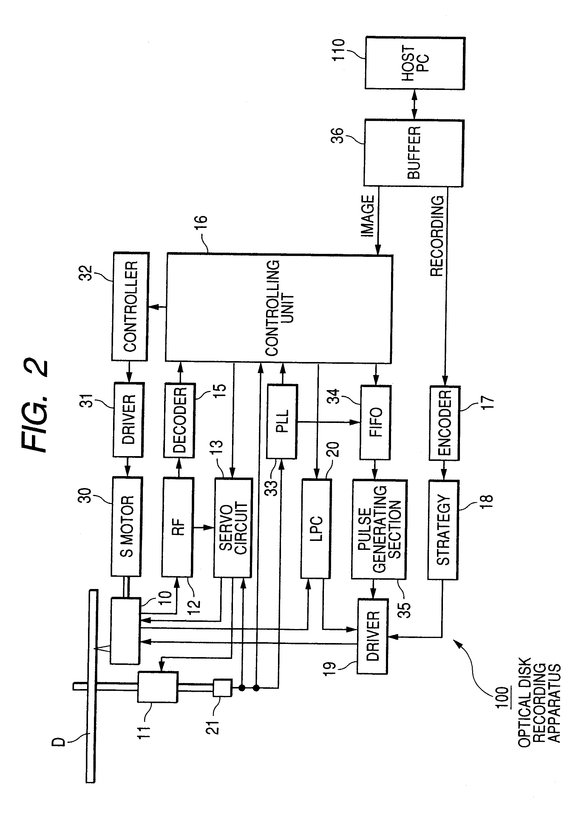
[0316]In the above-described embodiment, the laser light irradiation position is moved so that almost no gap is left all over the surface of the optical disk D by performing feed control of moving the optical pickup 10 in a given amount in the diameter direction on the peripheral side when a visible image is formed by irradiating with the laser light while the optical disk D makes one rotation starting from the standard position. However, there exists a case where the mechanism of driving the optical pickup 10 in the diameter direction cannot control the driving amount in the unit of 20 μm. With an optical disk recording apparatus having such driving mechanism, area of spaces on the optical disk D which cannot be irradiated with the laser light increases and, as a result, quality of the visible image formed in the visible image-recording layer of the optical disk D becomes deteriorated.

[0317]Therefore, in the case where the driving means for moving the optical pickup D in the diamet...

modified example 3

[0319]Also, while the optical disk recording apparatus 100 of the above embodiment employs a CAV system wherein the laser light is emitted toward the optical disk D rotated at a constant angular velocity to form a visible image, there may be employed a CLV system wherein the linear velocity of the optical disk D is constant. As has been described hereinbefore, in the case of employing the CAV system, it is necessary to increase the write level of the irradiated laser light as the laser light irradiation position moved toward the peripheral side of the optical disk D in order to form a visible image with high quality. With the CLV system, however, it is not necessary to change the write level value. Therefore, it never occurs that image quality of an image formed in the visible image-recording layer of the optical disk D is deteriorated due to variation of the target laser power value.


PUM


Abstract

An optical information recording medium comprises: a recording layer capable of recording and reproducing information by irradiation with a laser light; and an image recording layer capable of recording a visible image and containing a dye as a major component.

Description

TECHNICAL FIELD[0001]The present invention relates to an optical image recording medium and, in particular, to an optical information recording medium having an image recording layer capable of recording a visible image in addition to an optical information recording layer (preferably on the opposite side to the optical information recording side), an image recording method of recording an image on the optical information recording medium, and a method of utilizing a dye in the image recording layer.BACKGROUND ART[0002]Optical information recording media (optical disks) capable of recording information for once using a laser light have conventionally been known. The optical disks are also referred to as write-once CDs (so-called CD-Rs) and, in a typical structure thereof, a recording layer containing an organic dye, a reflection layer containing a metal such as gold and a protective layer made of a resin are laminated successively in this order on a transparent disk-shape substrate....

Claims


Application Information

Patent Timeline
IPC IPC(8): G11B7/00G11B7/24094G11B7/24097G11B7/2495
CPCG11B7/0037G11B2007/24612G11B7/246G11B7/2463G11B7/2467G11B7/2472G11B7/2478G11B7/248G11B7/2492G11B7/2495G11B7/2531G11B7/2533G11B7/2534G11B7/2535G11B7/256G11B7/259G11B23/40G11B7/245B41M5/26
Inventor MIKOSHIBA, HISASHISHIBATA, MICHIHIRO
Owner FUJIFILM CORP
Why Eureka
Try Eureka