Method for intermittently applying thin-film coatings

Active Publication Date: 2009-04-09
PANASONIC CORP
View PDF2 Cites 12 Cited by
  • Summary
  • Abstract
  • Description
  • Claims
  • Application Information

AI Technical Summary

Benefits of technology

[0012]To achieve the aforementioned object, a method for intermittently applying thin-film coatings according to the present invention provides control as follows. That is, a band-shaped substrate is looped on the backside thereof over a stationary reference roller and an actuation roller, which are disposed oppositely in parallel to each other; a portion to be applied with a coating agent is supported in parallel to the reference roller and the movable actuation roller and allowed to travel in one direction; and an application roller carrying a coating agent is brought into contact with the substrate halfway between the reference roller and the actuation roller so that the coating agent is transferred and deposited onto the surface of the substrate to thereby deposit and form a coating of thin film. Then, the actuation roller is moved with a predetermined timing to be retreated from the backside of the substrate to thereby separate the substrate from the application roller, and in synchronization with this, a tension roller is moved to advance towards the frontside of the substrate and thereby provide tension on the substrate. After that, the actuation roller is moved with a predetermined timing to be advanced towards the frontside of the substrate to bring the substrate into contact with the application roller; and in synchronization with this, the tension roller is moved to be retreated from the backside of the substrate to reduce the tension exerted on the substrate, and to form the thin film on the surface of the substrate on an intermittent basis. Then, for the tension applied to the substrate to be kept constant all the time, the tension roller is moved to be retreated from the backside of the substrate and to be advanced towards the frontside thereof so as to follow the actuation roller being moved to be retreated from the backside of the substrate.
[0024]Furthermore, in any one of the aforementioned methods, a trailing edge portion of the thin film in the direction of travel of the substrate may be formed in the shape of a straight line along the width of the substrate and in a swelling shape that is slightly thicker than a predetermined film thickness. In particular, when the methods are applied to the steps of manufacturing battery electrode plates, the trailing coating edge of the porous protective film deposited and formed as a thin film may take a swelling shape, even in the case of which this swelling shape is formed on the substrate behind the trailing coating edge of the active material layer that is deposited and formed as the coating deposit layer. Thus, the tip of the swelling shape would never be higher than the top surface of the active material layer, and thus this will not inhibit its use as the battery electrode plate without causing any problem.

Problems solved by technology

However, any one of the aforementioned intermittent coating methods is suitable to efficiently deposit and form a coating of thin film relatively as thick as 20 μm or greater, but cannot be employed, due to its configuration, to form a porous protective film with a thickness of 20 μm or less for use such as for battery electrode plates.
However, in Patent Document 3, no description is made regarding an intermittent coating technique for intermittently applying coatings to form a thin film while non-coating deposited sections having no coating agent applied thereto are being provided.
However, this method involves an unnecessarily complicated arrangement for allowing the substrate 40 and the gravure roll 43 to come into or out of contact with each other, resulting in its responsivity being significantly reduced.
Furthermore, as shown in FIGS. 10A to 10B, the aforementioned bad responsivity during intermittent coating operation causes the substrate 40 and the gravure roll 43 to come into or out of contact with each other with bad stability.

Method used


Image

  • Method for intermittently applying thin-film coatings
  • Method for intermittently applying thin-film coatings
  • Method for intermittently applying thin-film coatings

Examples


Embodiment Construction

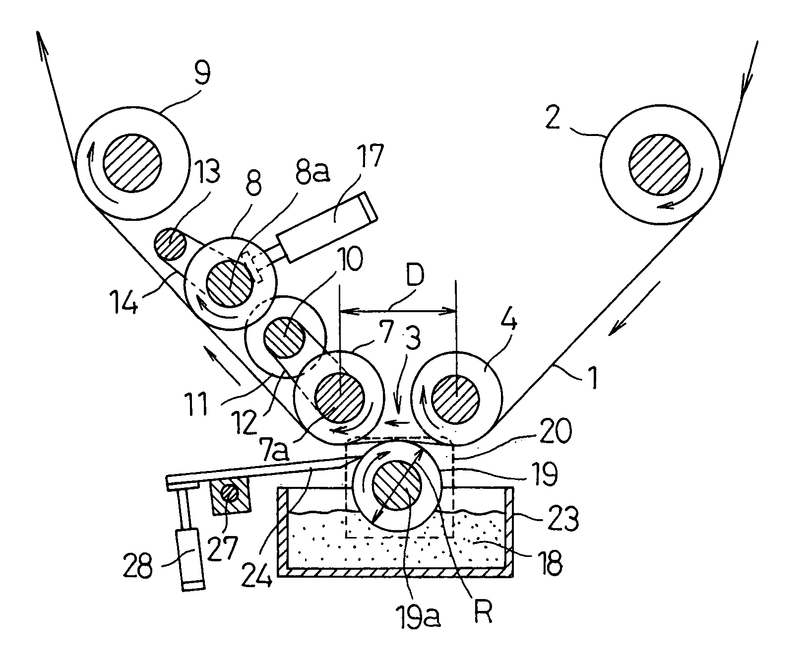
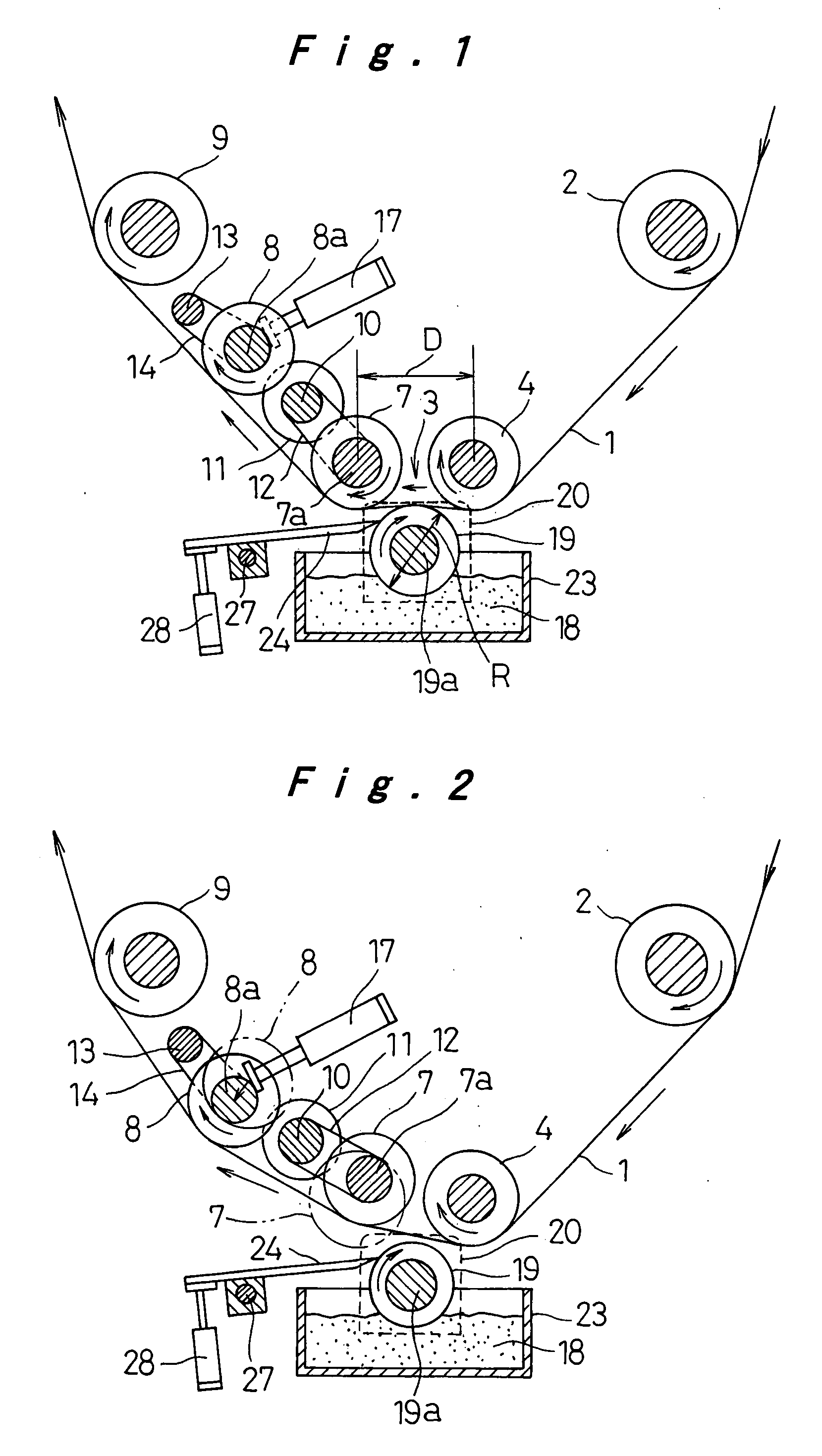
[0035]A description will now be made to the present invention with reference to the accompanying drawings in accordance with the embodiments. FIGS. 1 and 2 are schematic longitudinal sectional views illustrating an intermittent coating apparatus which embodies a method for intermittently applying thin-film coatings according to an embodiment of the present invention. FIGS. 1 and 2 show a coating of thin film being deposited and a coating of thin film being not deposited, respectively. A substrate 1 is a thin sheet shaped like a band, and in this embodiment, the substrate 1 is allowed to travel from the right to the left in the figure as indicated with the arrows. That is, the substrate 1 is paid out from a feed, roll on the right of the figure (not shown); guided by the feed guide roller 2 to a coating station 3; allowed to travel horizontally with its backside looped under tension between a reference roller 4 and an actuation roller 7; and in the subsequent stage, while being held ...


PUM

PropertyMeasurementUnit
Thicknessaaaaaaaaaa
Diameteraaaaaaaaaa
Diameteraaaaaaaaaa

Abstract

A method for intermittently applying thin-film coatings is realized, by which a coating of extremely thin film reduced to 20 μm or less in thickness is deposited intermittently with high productivity and at the same time, the trailing coating edge of the thin film is formed in a highly accurate shape having good linearity. This is achieved as follows. A band-shaped substrate (1) traveling in one direction is kept looped over a stationary reference-roller (4) and a movable actuation roller (7), and is brought into contact with an application roller (19) which carries a coating agent (18) on its circumferential surface and rotates in a direction opposite to the direction of travel of the substrate (1). The actuation roller (7) is moved to come into or out of contact with the substrate (1) with a predetermined timing. A tension roller (8) is also controllably moved to come into or out of contact with the substrate (1), following the actuation roller (7) coming into or out of contact with the substrate (1), so that the tension applied to the substrate (1) is kept constant all the time.

Description

TECHNICAL FIELD[0001]The present invention relates to a method for intermittently applying thin-film coatings, which is suitably used for depositing a coating of thin film, on the surface of a substrate shaped like an extra long sheet, in a predefined pattern in which coating deposited sections and non-coating deposited sections are present alternately intermittently.BACKGROUND ART[0002]Recently, to manufacture electronic components such as semiconductor devices or capacitors, a thin-film coating of paint or the like is fairly often deposited in a pattern on the surface of a band-shaped substrate. For example, it has been suggested for battery electrode plates that an active material layer is formed on the surface of a collector serving as a substrate, and then a porous protective film with a thickness of 0.1 μm to 200 μm or a porous protective film of coating film containing a resin binder and fine particulate solids such as alumina powder is formed to cover the aforementioned acti...

Claims


Application Information

Patent Timeline
IPC IPC(8): B05D1/28B05D3/12B05D7/14B65H23/188
CPCB05C1/0826B05C1/12B05C1/165B05D1/28Y02E60/122H01M4/0409H01M4/139H01M10/0525H01M4/0404Y02E60/10H01M4/04
Inventor TERAMOTO, KAZUTAKAHAYASHI, TETSUYA
Owner PANASONIC CORP
Why Eureka
Try Eureka